00193891-0702_AI_LP_Barcode_DE+EN.pdf - 第191页
SIPLACE 2 PCB barcode scanner assembly instructions 10/2009 Edition 2.7 Installing the PCB barcode scanner 191 Electrical connection S-27 HM 2 : Remove the plexigl as cover from the conveyor control. : Remove the two scr…
2 PCB barcode scanner assembly instructions SIPLACE
2.7 Installing the PCB barcode scanner 10/2009 Edition
190
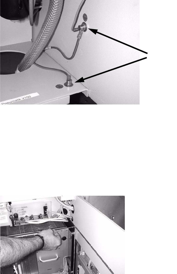
: Connect the grounding cable for the distributor rail to the available grounding points.
Grounding points
2
2
: Slide the barcode control cable through the machine frame (using a suitable tool if necessary)
to the module on the other side of the machine.
S-27 HM
Cable no.: 03016827-01
F4, F5, F5 HM, S-20, S-23, S-25 HM
Cable no.: 00373479-01
2
: Open the door of the module on the other side of the machine, to the left as viewed in the di-
rection of travel.
: Undo the module screw, remove the module and place it carefully on the floor.
2
2
SIPLACE 2 PCB barcode scanner assembly instructions
10/2009 Edition 2.7 Installing the PCB barcode scanner
191
Electrical connection S-27 HM 2
: Remove the plexiglas cover from the conveyor control.
: Remove the two screws and three socket-head pins
from the conveyor control and remove it..
2 screws
3 socket-head pins
2
: Plug the barcode connection cables into the top of the conveyor control.
Barcode connection cables
2

2 PCB barcode scanner assembly instructions SIPLACE
2.7 Installing the PCB barcode scanner 10/2009 Edition
192
The jumper assignment for the interface (SIPLACE / SMEMA) on the conveyor control must cor-
respond to the current interfaces
otherwise the barcode data will not be forwarded correctly to the
station software. 2
J1 = SIPLACE/SMEMA up
stream station
J2 = SIPLACE/SMEMA downstream station
SIPLACE = setting 1-2; SMEMA setting 2-3. 2
2
: Refit the conveyor control.
: Slid
e the excess cable length into the machine frame.
: F
asten the plexiglas cover of the conveyor control, slide the module back in, screw it in place
and close the module door.
2
Electrical connections F4, F5, F5 HM, S-20, S-23, S-25 HM 2
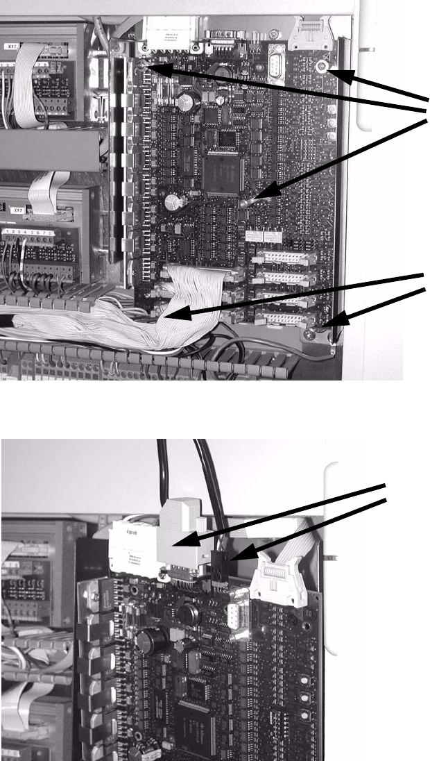
: Pu
ll the cable with the plug W2 towards the machine controller and plug it in as follows (see
photo):
– Cable 00373479 into port COM 2 of the machine controller on F4, F5, F5 HM, S-20 and S-
2
3 machines (1) .
– Cable 00373479 into X5sa of the conveyor control TSP-210 on S-25 HM machines (2).
: Pu
ll the cable W1 towards the terminal board and connect it as shown in the wiring diagram
"PCB S/F barcode wiring "
Chapter 2.9.