00193891-0702_AI_LP_Barcode_DE+EN.pdf - 第193页
T erminal panel SIPLACE 2 PCB barcode scanner assembly instructions 10/2009 Edition 2.7 Installing the PCB barcode scanner 193 2 The jumper assignme nt for the interface (SIPLACE / SMEMA) on the co nveyor control must co…

2 PCB barcode scanner assembly instructions SIPLACE
2.7 Installing the PCB barcode scanner 10/2009 Edition
192
The jumper assignment for the interface (SIPLACE / SMEMA) on the conveyor control must cor-
respond to the current interfaces
otherwise the barcode data will not be forwarded correctly to the
station software. 2
J1 = SIPLACE/SMEMA up
stream station
J2 = SIPLACE/SMEMA downstream station
SIPLACE = setting 1-2; SMEMA setting 2-3. 2
2
: Refit the conveyor control.
: Slid
e the excess cable length into the machine frame.
: F
asten the plexiglas cover of the conveyor control, slide the module back in, screw it in place
and close the module door.
2
Electrical connections F4, F5, F5 HM, S-20, S-23, S-25 HM 2
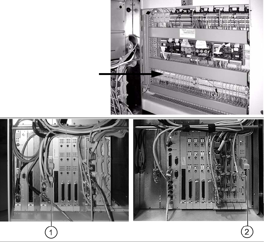
: Pu
ll the cable with the plug W2 towards the machine controller and plug it in as follows (see
photo):
– Cable 00373479 into port COM 2 of the machine controller on F4, F5, F5 HM, S-20 and S-
2
3 machines (1) .
– Cable 00373479 into X5sa of the conveyor control TSP-210 on S-25 HM machines (2).
: Pu
ll the cable W1 towards the terminal board and connect it as shown in the wiring diagram
"PCB S/F barcode wiring "
Chapter 2.9.
Terminal panel
SIPLACE 2 PCB barcode scanner assembly instructions
10/2009 Edition 2.7 Installing the PCB barcode scanner
193
2
The jumper assignment for the interface (SIPLACE / SMEMA) on the conveyor control must cor-
respond to the current interfaces otherwise the
barcode data will not be forwarded correctly to the
station software. 2
J1 = SIPLACE/SMEMA upstream station
J2 = SIPLACE/SMEMA downstream station
SIPLACE = setting 1-2
;
SMEMA setting 2-3. 2
: Swing the pneu
matic unit back (on the other side of the machine) and screw it on.
2
2 PCB barcode scanner assembly instructions SIPLACE
2.7 Installing the PCB barcode scanner 10/2009 Edition
194
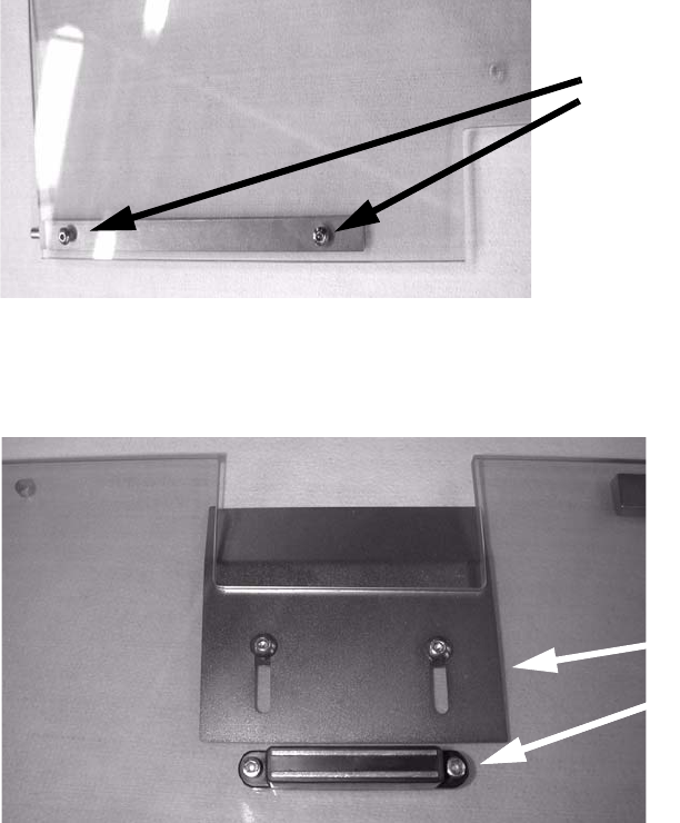
Fitting the protective cover 2
: Remove the film from the new protective cover and its components.
: Use the hing
es from the old cover for the new one.
Remove the white packing discs from the sides.
Screw a hinge onto the cover.
2 screws
2
2
: Screw the protective plate and magnet to the protective cover.
Protective plate
MagnetMagnet
2
2
: Remove the cover switch actuator from the old cover and fit it onto the new one. Only do the
screws up loosely so that the actuator can be accurately positioned later.
2
2
2
2
2