00193891-0702_AI_LP_Barcode_DE+EN.pdf - 第211页
Wire color / wire no. Type Cross-section / hole gnye 1.5 mm² / 5 F Important: Shrink cab les sepa rately when they are no t connected. Wire connection technolog y A: Wire end ferrule C: Crimp c ontact C/So: Crim p contac…
Lw1
Connector 1
Connector 2
Dimensions / cable type
Cable W1 dimensions
Basic length acc. to parts list
Assembled overall length / tolerance
Inscription label
Cable type:
Option:
Material number:
Lw1
L3w1
L in mm
Stripped length
L1w1
L2w1
approx. 20mm
beneath the shrink-fit sleeve
L1w1 L3w1
L2w1
Dimension / connector designation / labeling
The arrow always points to the upper left corner of the inscription label.
For details concerning the inscription and design of the labels,
please refer to the inscription guidelines for cable sets which you will find included in the parts list.
Important:
Shrink cables separately when they are not connected.
Wire connection technology
A: Wire end ferrule
C: Crimp contact
C/So: Crimp contact, socket
C/CO: Crimp contact, connector
F: Flat pin bushing
L: Soldered joint
CR: Cable lugs (ring-type)
CP: Cable lugs (pin)
CF: Cable lugs (fork-type)
SA: Screen assembly
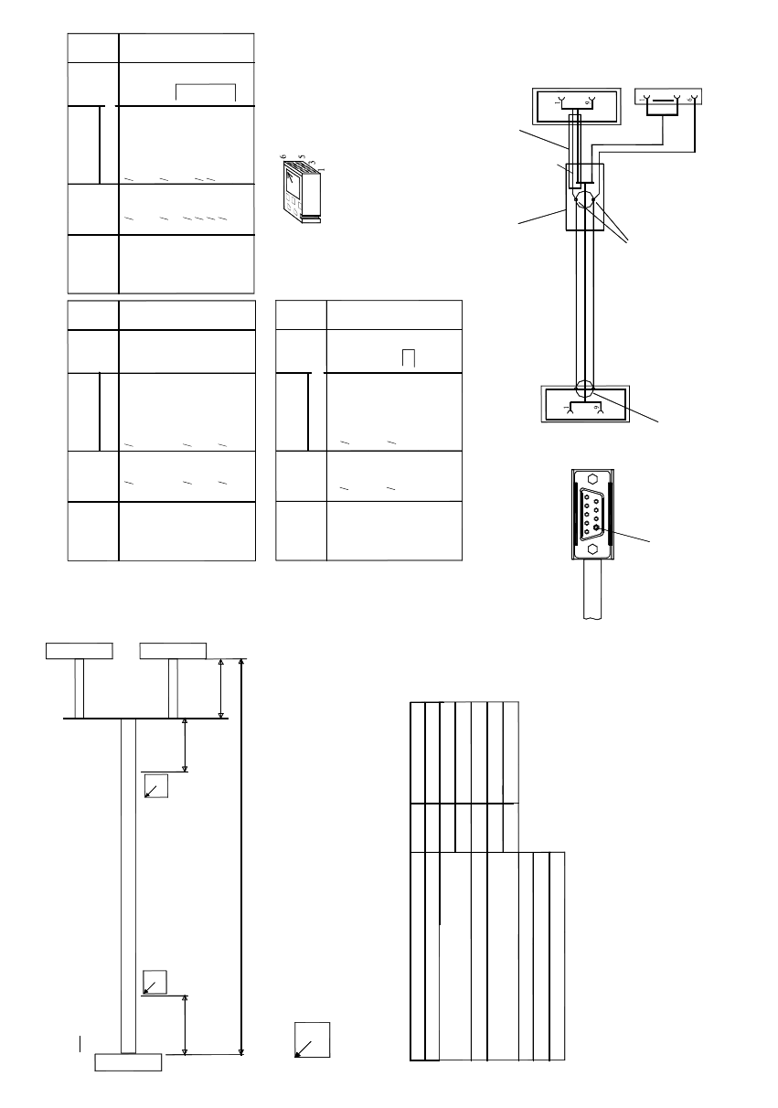
Unitronic LIYCY, 6x0.25mm²
03016825-xx
30
100
600/+50
700
30
Wire
color /
Wire no.
Conn. desig.
Connector 1:
X5
Pin
Conn. technology
Type Cross-section
Jumpers KEY
Wiring
1
2
3
4
5
6
7
8
9
wh
bn
gn
ye
gy
pk
C / SO 0.15-0.40
C / SO 0.15-0.40
C / SO 0.15-0.40
C / SO 0.15-0.40
C / SO 0.15-0.40
C / SO 0.15-0.40
Wire
color /
Wire no.
Conn. desig.
Connector 2:
X23ao
Pin
Conn. technology
Type Cross-section
Jumpers KEY
1
2
3
4
5
6
7
8
9
ye
gy
pk, bk
Screen
Connector 1: SUB-D 9-pole, female
bk
Screen with connector 2/pin 5
and connector 3/pin 6 connected.
Solder onto screen
Fit screen to SUB-D
casing with contact sleeve
A6107
Connector 1
w1
Connector 1, connector 2
Orientation of the cable exit
Connector 3
C / SO 0.15-0.40
C / SO 0.15-0.40
C / SO 0.15-0.40
C / SO 0.15-0.40
C / SO 0.15-0.40
Connector 2
Connector 3
Shrink-fit sleeve
upto and in the connector casing
Connector 2: SUB-D 9-pole, female
Connector 3: Locking clip, 6-pole
Make sure that ....
the numerical sequenceof a locking-clip plug
must be as viewed from the rear side of the casing.
Wire
color /
Wire no.
Conn. design.
Connector 3:
X24ao
Pin
Conn. technology
Type Cross-section
Jumpers KEY
1
2
3
4
5
6
0.12-0.56
0.12-0.56
0.12-0.56
0.12-0.56
C/SO
C/SO
C/SO
C/SO
X
X
wh
bn
gn
bk
Screen
Coding pin (for connector 1)
w1
w1
Sheath end shrink-fitted,
Length for shrink-fitted sleeve
bk
2 PCB barcode scanner assembly instructions SIPLACE
2.9 Electrical drawings 10/2009 Edition
210
2
Fig. 2.9 - 11 Cables for distributor for PCB barcode scanner HS-50 / HS-60 (03016825-010102)
Wire color / wire no. Type Cross-section / hole
gnye 1.5 mm² / 5 F
Important:
Shrink cables separately when they are not connected.
Wire connection technology
A: Wire end ferrule
C: Crimp contact
C/So: Crimp contact, socket
C/CO: Crimp contact, connector
F: Flat pin bushing
L: Soldered joint
CR: Cable lugs (ring-type)
CP: Cable lugs (pin)
CF: Cable lugs (fork-type)
SA: Screen assembly
Side 1
Connection technology
Wire color / wire no. Type Cross-section / hole
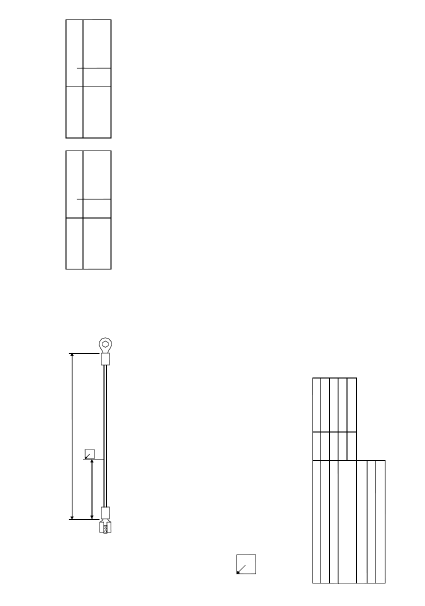
gnye 1.5 - 2.5 mm² / M4CR
Side 2
Connection technology
Side 1
Side 2
Lw1
L2w1
90
Dimension / connector designation / labeling
The arrow always points to the upper left corner of the inscription label.
For details concerning the inscription and design of the labels,
please refer to the current TBL (technical ordering designations and terms of supply).
Dimensions / cable type
Cable W1 dimensions
Basic length acc. to parts list
Assembled overall length / tolerance
Inscription labels
Cable type:
Option:
Material number:
Lw1
L2w1
L in mm
Wiring
03012264-01
200
180/+10
W1
H05V-K, UL-CSA 1.5 mm² gnye
SIPLACE 2 PCB barcode scanner assembly instructions
10/2009 Edition 2.9 Electrical drawings
211
2
Fig. 2.9 - 12 Grounding cable for distributor for PCB barcode scanner HS-50 / HS-60 (03022264-010101)
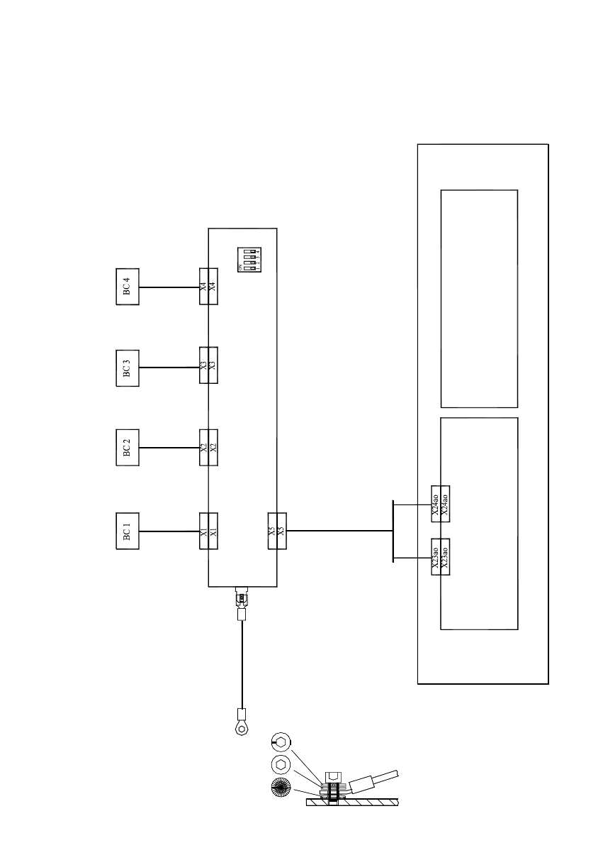
Distributor f. PCB barcode scanner 00372356-xx
Barcode scanner
top
Conveyor track 1
Barcode scanner
bottom
Conveyor track 1
Barcode scanner
top
Conveyor track 2
Barcode scanner
bottom
TConveyor track 2
Control assy, PCB conveyor (single conveyor: 00363359-xx, dual conveyor: 00363360-xx)
Conveyor control, track 1
(ao) 00370397-xx
Conveyor control, track 2
(ap) 00370398-xx
(for dual conveyor only)
If no barcode scanner is connected to X1 ... X4,
PCB barcode, conveyor track 1
PCB barcode, conveyor track 2
(for dual conveyor)
S1
03016825-xx
03022264-01
Extension kit
Frame
Distributor grounding terminal
Wiring for HS60/D4 single/dual conveyor
*)
*)
make sure to set the associated switch contact 1 ... 4 at S1 to ON.
2 PCB barcode scanner assembly instructions SIPLACE
2.9 Electrical drawings 10/2009 Edition
212
2
Fig. 2.9 - 13 Wiring for HS-60 / D4 single/dual conveyor