00193891-0702_AI_LP_Barcode_DE+EN.pdf - 第217页
SIPLACE 2 PCB barcode scanner assembly instructions 10/2009 Edition 2.10 Software configur ation 217 2.10 Sof tware configuration 2.10.1 Activation in the SITEST program : S tart SITEST . : Se lect "Setting s" …
Wire color / wire no. Type Cross-section / hole
gnye 1.5 mm² / 5 F
Important:
Shrink cables separately when they are not connected.
Wire connection technology
A: Wire end ferrule
C: Crimp contact
C/So: Crimp contact, socket
C/CO: Crimp contact, connector
F: Flat pin bushing
L: Soldered joint
CR: Cable lugs (ring-type)
CP: Cable lugs (pin)
CF: Cable lugs (fork-type)
SA: Screen assembly
Side 1
Connection technology
Wire color / wire no. Type Cross-section / hole
gnye 1.5 - 2.5 mm² / M4CR
Side 2
Connection technology
Side 1
Side 2
Lw1
L2w1
90
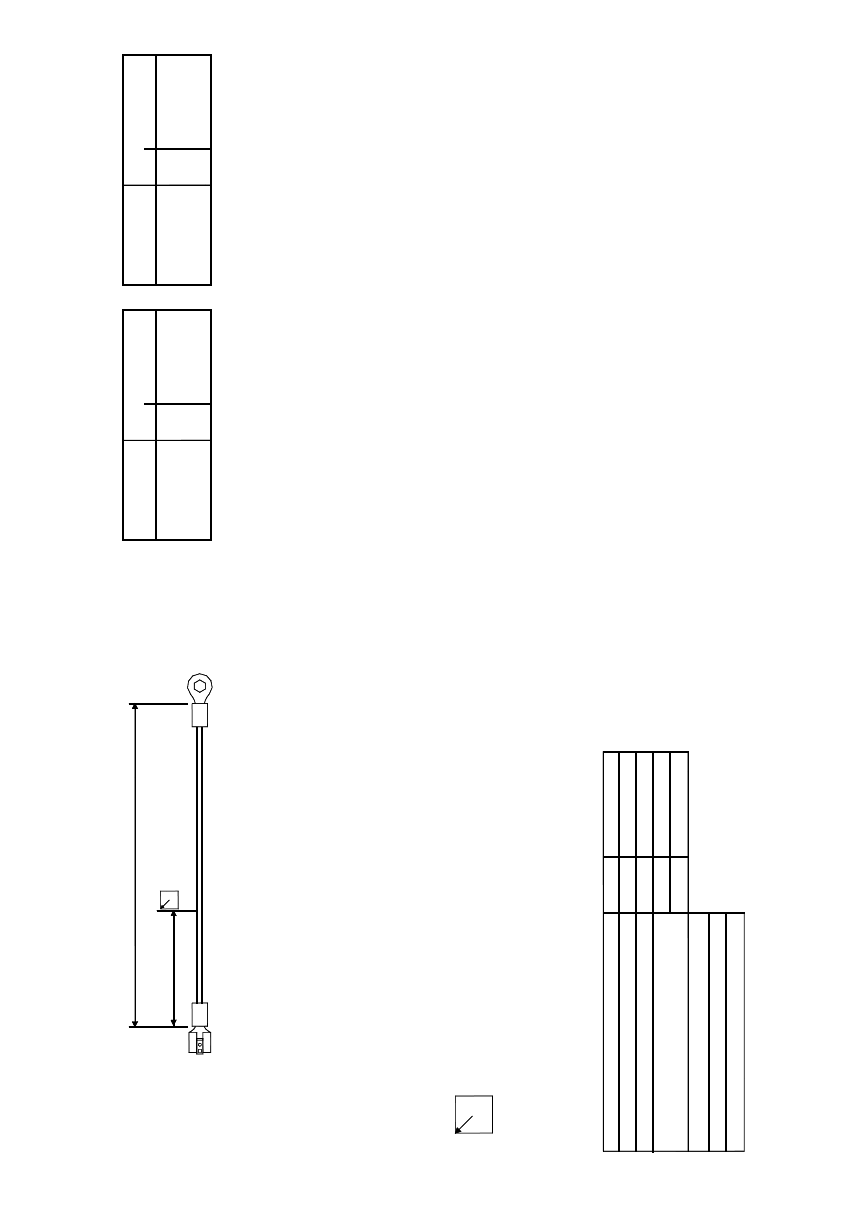
Dimension / connector designation / labeling
The arrow always points to the upper left corner of the inscription label.
For details concerning the inscription and design of the labels,
please refer to the current TBL (technical ordering designations and terms of supply).
Dimensions / cable type
Cable W1 dimensions
Basic length acc. to parts list
Assembled overall length / tolerance
Inscription labels
Cable type:
Option:
Material number:
Lw1
L2w1
L in mm
Wiring
03012264-01
200
180/+10
W1
H05V-K, UL-CSA 1.5 mm² gnye
2 PCB barcode scanner assembly instructions SIPLACE
2.9 Electrical drawings 10/2009 Edition
216
2
Fig. 2.9 - 17 Grounding cable: PCB barcode scanner distributor, HF (03012664-010101)
SIPLACE 2 PCB barcode scanner assembly instructions
10/2009 Edition 2.10 Software configuration
217
2.10 Software configuration
2.10.1 Activation in the SITEST program
: Start SITEST.
: Se
lect "Settings" --> "Machine Configuration".
: Set th
e PCB barcode conveyor track X to "default" according to the machine configuration.
: Clic
k on "Accept" twice and restart the machine.
2.10.2 Activate in SIPLACE PRO
: Start SIPLACE PRO.
: Se
lect "Properties" --> "Station" --> "PCB barcode".
: Clic
k on the "Line" button.
: Sel
ect "Properties" --> "Barcode scanner position".
: Sele
ct the barcode scanner position (top or bottom) for the conveyor track.
2 PCB barcode scanner assembly instructions SIPLACE
2.11 PCB barcode scanner configuration 10/2009 Edition
218
2.11 PCB barcode scanner configuration
2.11.1 General notes about the barcode
Today, increasing numbers of components, individual components, semi-finished and end prod-
ucts are being uniquely identifed with a barcode, whic
h makes them easier to check. This, in turn,
makes it easier to control production, stock-keep and to trace components in the event of errors.
Both one-dimensional (1D, e.g. barcodes) and two-dimensional (2D, e.g. data matrix codes)
codes can be used.
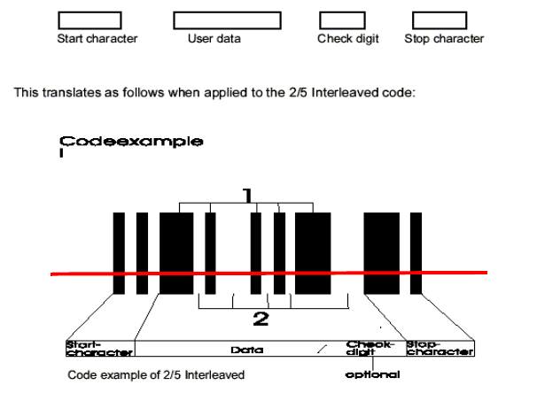
2.11.2 Structure of 1D barcodes
Barcode types include 2/5 interleaved, Codabar, Code 39, Code 128, EAN 8, EAN 13 for industrial
applications.
The 1D barcode scanner reads the barcode using a red light laser diode and a rotating mirror
whee
l, which creates a red scanning line that is visible to the human eye.
The structure of a barcode, the nu
mber of black lines and white gaps for each character to be
coded is fixed for each barcode type. The information is located in both the lines and the gaps of
a barcode but, in general, the following structure can be defined for a barcode.
Fig. 2.11 - 1 Structure of a 1D barcode
Advantages: - up to 50 characters can be encoded, depending on the type of code.
- barcodes can be read and scanned very re
liably with the optical scanning system
- barcodes are cheap to produce
- barcode scanners are very cheap to buy