00193891-0702_AI_LP_Barcode_DE+EN.pdf - 第238页
2 PCB barcode scanner assembly instructions SIPLACE 2.11 PCB barcode scanner configuration 10/2009 Edition 238 Fig. 2.1 1 - 30 Focus height set correctly : Click on "Next". 2.1 1.7.7 Dat aMatrix AutoSetup for a…
SIPLACE 2 PCB barcode scanner assembly instructions
10/2009 Edition 2.11 PCB barcode scanner configuration
237
2.11.7.6 Setting the focus height:
Now place a PCB with the "adjustment barcode" stuck on beneath the barcode scanner. The bar-
code scanner attempts to determine the distance between
the barcode lines and thus calculate
the current focus height. This is then displayed graphically and will have to be set mechanical (see
Fig. 2.11 - 29, Fig. 2.11 - 30 below).
PLEASE NOTE
The adjustment barcode for the focus heigh
t is not currently available.
You will have to check the focus height using the mechanical adjusting gauge.
Click on "Next" to skip this setting.
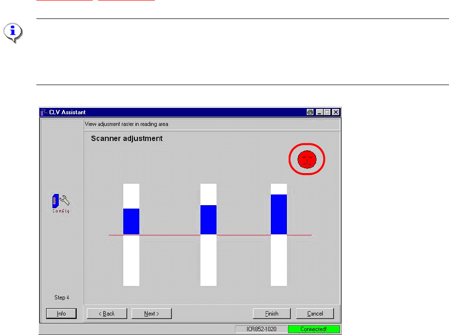
Fig. 2.11 - 29 Focus height not set correctly.
2 PCB barcode scanner assembly instructions SIPLACE
2.11 PCB barcode scanner configuration 10/2009 Edition
238
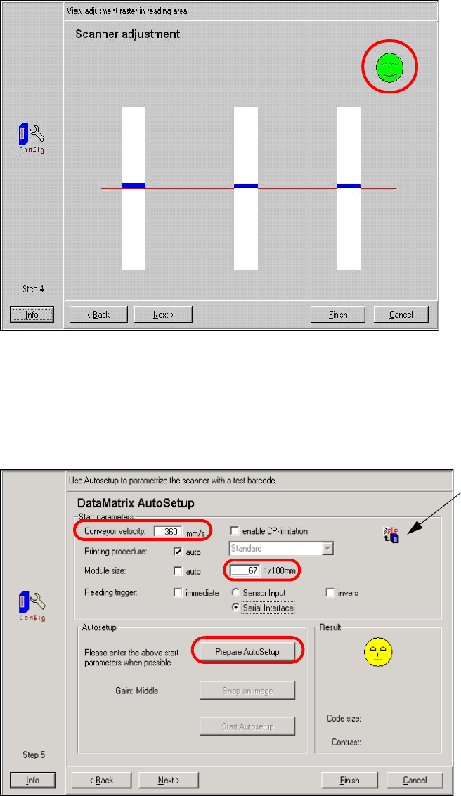
Fig. 2.11 - 30 Focus height set correctly
: Click on "Next".
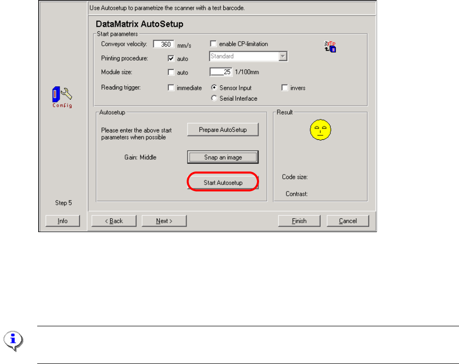
2.11.7.7 DataMatrix AutoSetup for automatically teaching a 2D barcode:
FTP program button
The FTP program is
used to record im-
ages of unscanned
barcodes, for exam-
ple, and analyze the
errors during start-up
or production
(See Requesting im-
ages during produc-
tion).
Fig. 2.11 - 31 Step 5 in the CLV Assistant
: Enter the conveyor velocity and the size of a matrix dot (module size).
SIPLACE 2 PCB barcode scanner assembly instructions
10/2009 Edition 2.11 PCB barcode scanner configuration
239
: Click on the "Prepare AutoSetup" button.
The velocity and module size are sent to the barcode scanner.
The "Snap an image" button is now active.
Requirements for snapping the image:
– The machine with the barcode scanner to be configured must be "Waiting for PCB".
– Press the STOP button on the upstream machine.
– Place a PCB with the barcode on the output belt of th
e up
stream machine so that the bar-
code is approximately 1 cm in front of the scanning beam.
: Click on the "Snap an image" button.
: Then press the START button on the upstream machine.
: The "Start Autosetup" butto
n should now be active.
Fig. 2.11 - 32 Step 5 in the CLV Assistant
: Click on the "Start Autosetup" button.
If the barcode is read successfully, the data for the con
veyor velocity, module size and optimization
parameters such as contrast, brightness, etc. are determined.
PLEASE NOTE:
These parameters should not be manually changed again.