00193891-0702_AI_LP_Barcode_DE+EN.pdf - 第246页
2 PCB barcode scanner assembly instructions SIPLACE 2.11 PCB barcode scanner configuration 10/2009 Edition 246 : Click on 2D Symbology Parameters Fig. 2.1 1 - 39 Barcode parameters 2 : The settings made in Fig. 2.1 1 - 3…
SIPLACE 2 PCB barcode scanner assembly instructions
10/2009 Edition 2.11 PCB barcode scanner configuration
245
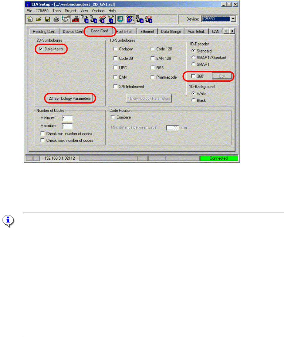
: Select the "Code conf." tab.
Fig. 2.11 - 38 Code configuration
2
: Check the Data Matrix check box.
Note on scanning 1D barcodes:
1. If the 2D barcode scanner also has to scan 1D barcode
s, then the appropriate barcode types
must be activated on the right-hand side. In th
is way, the hardware decoder is active and
the analysis takes place as for a normal 1D barcod
e scanner (provided that the barcode to
be scanned is placed crosswise on th
e PCB thus allowing fast analysis).
2. Check the 360° check box. This switches off the hard
ware decoder so that the analysis takes
place via the image analysis, as for a 2D barcode. If the 360° check box is checked, then
the maximum bar thickness and height of the 1D
barcodes used must be entered under the
"Edit" button. The barcode may be positioned as requir
ed on the PCB (although this may
extend the analysis time).
3. If the "Use binary information" check box is checke
d in the "Edit" menu, the hardware decoder
is switched on again. If it is unable to read the ba
rcode, then an attempt is made to read the
barcode using the image analysis (long analysis times are possible).
2
2
2 PCB barcode scanner assembly instructions SIPLACE
2.11 PCB barcode scanner configuration 10/2009 Edition
246
: Click on 2D Symbology Parameters
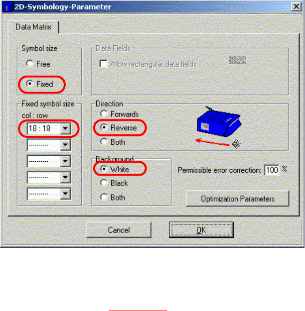
Fig. 2.11 - 39 Barcode parameters
2
: The settings made in Fig. 2.11 - 39 apply to the "DEMO" example.
: Fixed symbol size indicates the number of columns and rows in the Data Matrix barcode.
: The Scanning is always reverse when used on the Siplace.
: Background defines the colored background of the 2D barcode.
2
2
2
2
2
2
2
2
2
2
SIPLACE 2 PCB barcode scanner assembly instructions
10/2009 Edition 2.11 PCB barcode scanner configuration
247
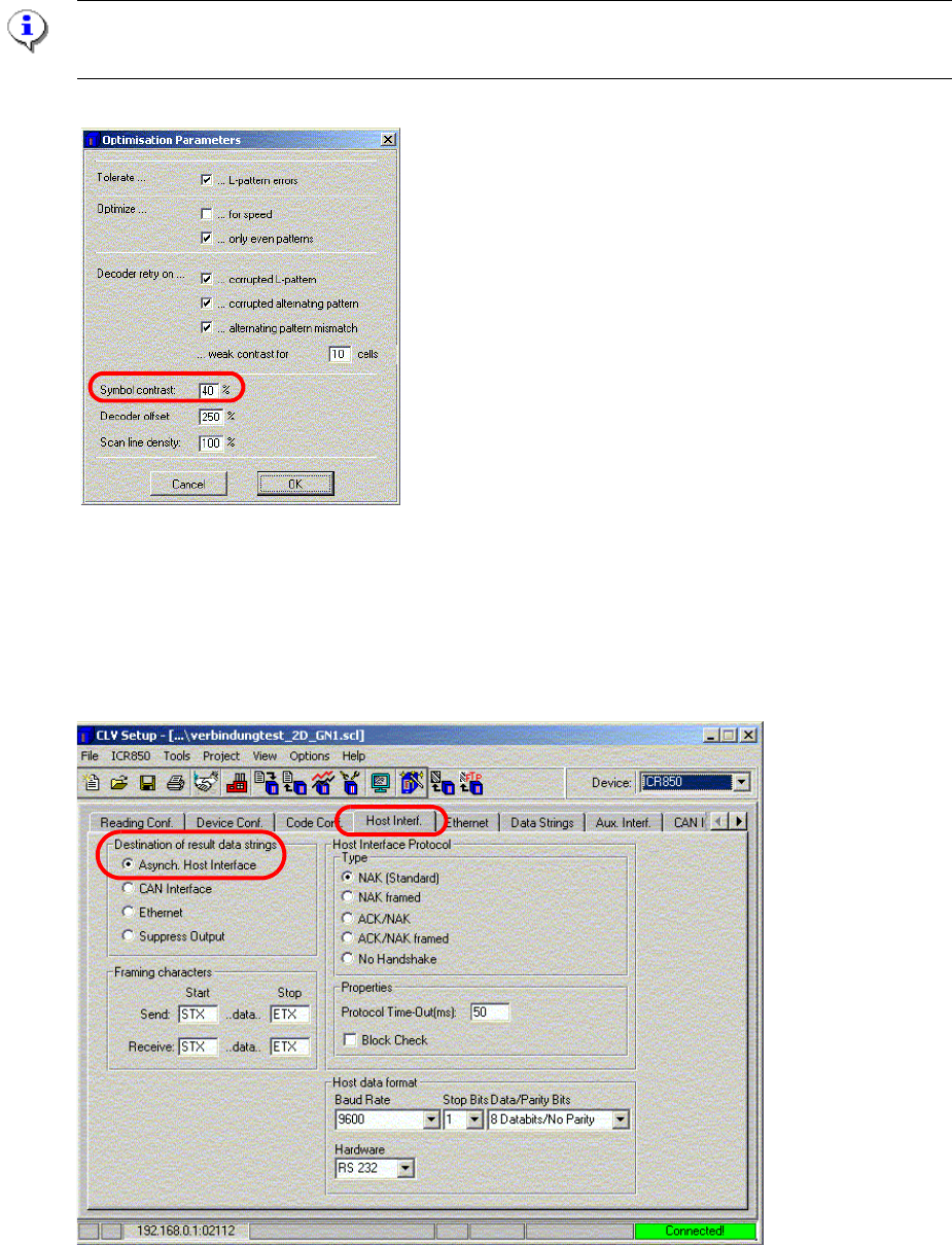
: Click on "Optimization Parameters".
Please note:
This parameter must not be changed if it was set using the CLV Assistant.
Fig. 2.11 - 40 Optimization parameters
: Symbol contrast is used to adapt the image quality to suit the specific barcode.
: Click on OK to confirm your input.
: Select the "Host Interf." tab.
Fig. 2.11 - 41 Host interface