00193891-0702_AI_LP_Barcode_DE+EN.pdf - 第264页
2 PCB barcode scanner assembly instructions SIPLACE 2.12 Tips & tricks for the barcode scanner 10/2009 Edition 264 The analysis time is the time from when the scann er is switched on until the barcode is success - fu…
SIPLACE 2 PCB barcode scanner assembly instructions
10/2009 Edition 2.12 Tips & tricks for the barcode scanner
263
– The “CLV Wizard“ button is used to check or set the focus height of the barcode reader and
automatically configure it for a certain barcode type.
2
For further information, see section 6 / Changes in the CLV Wizard. 2
2
2
– The “FTP image output" button is used to display the image read by the scanner on the com-
puter.
2
The diagnostic data must have been activated in the “Image request“ menu in order to show the
guiding lines. 2
2
2
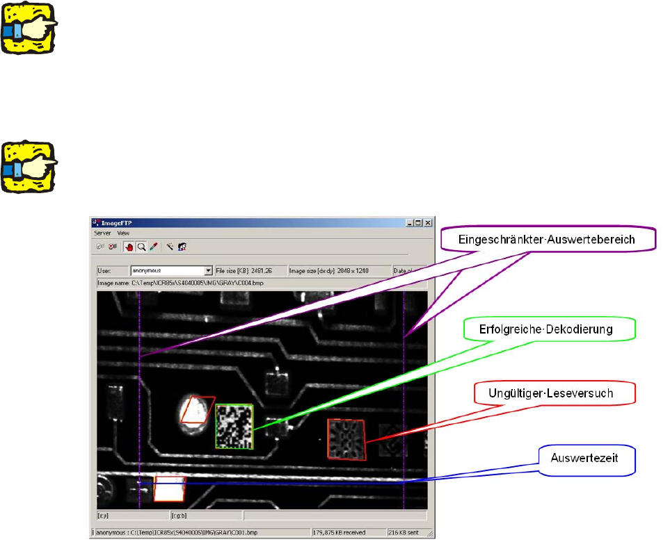
2.12.6.1 How the ICR850 works
When it is switched on, the scanner looks for possible barcode structures. 2
When it detects a possible structure, it places a barcode grid over it. 2
If the grid does not conform to the specifications, th
en the
structure is given a red border to indi-
cate an invalid scan attempt
. 2
If it does conform to the specifications, the bar
code is decoded, given a green border and output
to at the station. 2
The violet dashed lines restrict the area that the scan
ner analyzes when searching for the bar-
code. 2
2 PCB barcode scanner assembly instructions SIPLACE
2.12 Tips & tricks for the barcode scanner 10/2009 Edition
264
The analysis time is the time from when the scanner is switched on until the barcode is success-
fully decoded. The closer the blue line is to the su
ccessfully-decoded barcode, the better the pre-
set values. 2
2.12.7 Analyzing the data string in the terminal monitor
TT
The analysis time depends entirely on the application and is the time from the start of
the scan window to the end of the scan window, so it can extend over the entire length
of the PCB.
The result must be output in SIPLACE either immed
iately or after a time set with a timer,
and must thus be shorter than the external scan window.
MG
This value is not very informative and it comes from the linear codes.
n
Scanner status (0 = no code scanned)
2
2
The second line is the entire data content of the data matrix code. 2
DATX
Data matrix code detection
ST
Scan status (0 = Code detected as correct)
SZ
Shows the symbol size and the number of working bits. The last two values are the
number of pixels or the scans per cell. If the two values are identical on average, the
speed has been set correctly.
CT
Two values are output as a contrast; the first value shows the grayscale difference in
the data matrix symbol. A value in excess of 200 is good and the maximum possible
value is 255. This is not desirable, however, since the amplifiers are saturated at 255.
EC
For these values, the second digit is actually the important one as it shows the
percentage usage of the redundant data bytes. 100% is critical here and shows that the
NOREAD limit has been reached. It can be tolerated in individual cases, however, but
it should not exceed 50% on average.
PT
For PT, the coordinates of the three corner points of the L pattern of the data matrix
symbol are output. This is of less relevance in the SIPLACE application, but it can be
important in applications in which there are several codes to be scanned in the scanning
window in order to determine which codes were read. The first value is the pixel position
on the line, while the second value is the number of scans since the start of the scanning
window.
2
2
2
The two most important criteria are EC (percentage) and CT (contrast). 2
SIPLACE 2 PCB barcode scanner assembly instructions
10/2009 Edition 2.12 Tips & tricks for the barcode scanner
265
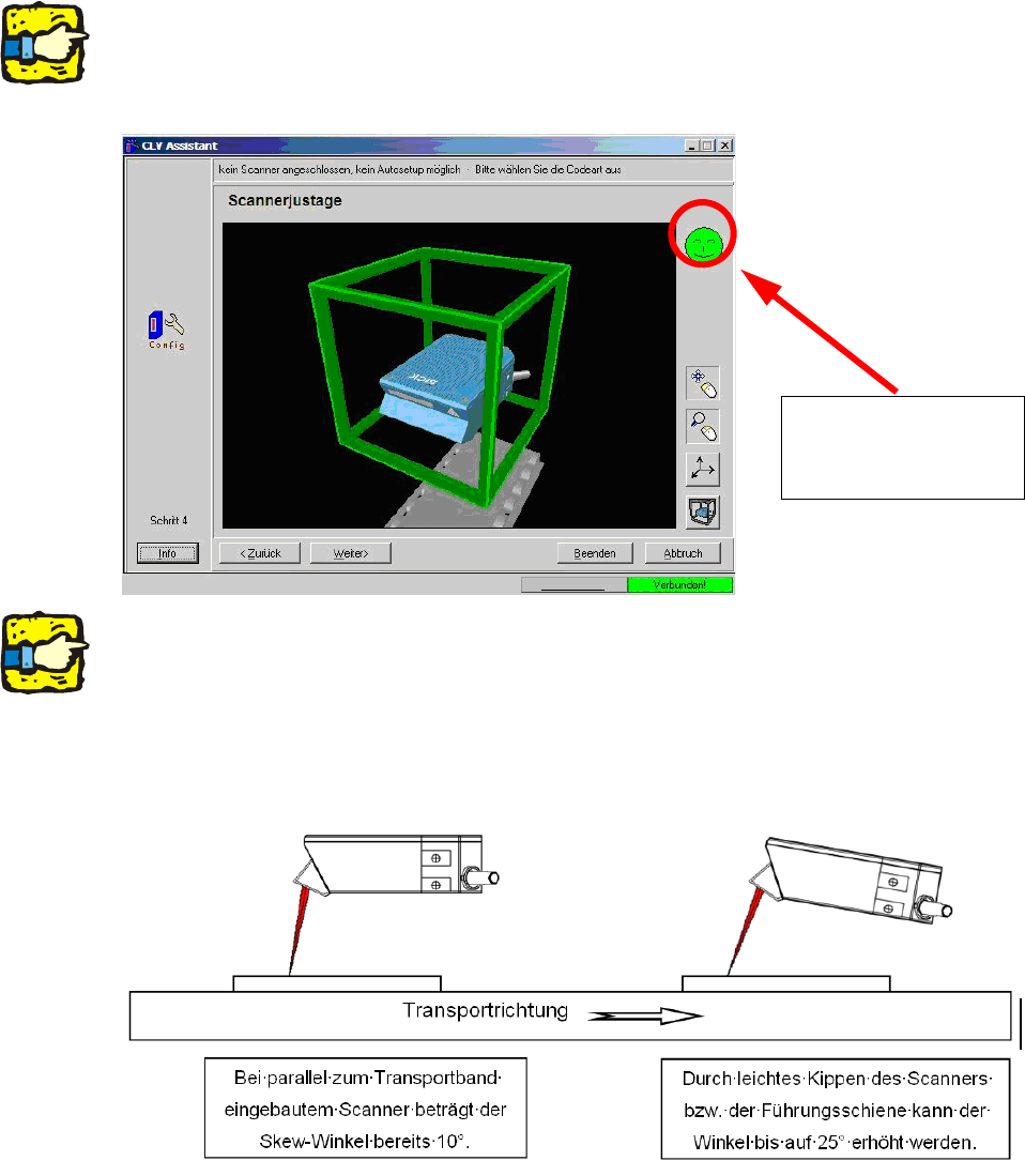
2.12.8 Changes in the CLV wizard
The graphical representation for setting the scanners and the focus height have changed in ver-
sion 4.2 of the CLV Setup software. 2
2
For a detailed description, see:
00193891-xx Retrofit instructions for PCB barcode, se
ction 1.11.6.5 Working with the CLV wiz-
ard 2
The illustration shows
the display if the scan-
ner is set correctly.
2
2
If problems occur when scanning data matrix code, even though the scanner is set correctly, then
the scanner should be set up with a skew angle of up to 25°. 2
This is particularly recommended
with low-contrast codes (e.g. CO2 or Nd-YAG lasered). 2
In this case, the focus height can
not be determined using the CLV wizard, however, and must be
set manually using the gauge supplied. 2
2