SPF维修.pdf - 第147页
SPF 6.7 Secret Screen Service Functions (CONFIDENTIAL) SERVICE MANUAL 6.7−16 D54SEC−85−080−A0 MANUAL : 1BLOCK <<MACHINE INITIAL SETTING>> XXXX−XX−XX XX:XX F1 F2 F3 F4 F5 F6 F7 F8 [RECOGNITION SERVICE] COMPLET…
6.7 Secret Screen Service Functions (CONFIDENTIAL)
SERVICE MANUAL
SPF
6.7−15
D54SEC−85−080−A0
MANUAL : 1BLOCK
<<MACHINE INITIAL SETTING>>
XXXX−XX−XX XX:XX
F1
F2
F3 F4 F5
F6
F7 F8
[RECOGNITION SERVICE]
COMPLETE
PCB CAMERA
SCREEN
CAMERA
PCB CAMERA
DISPLAY MODE
ORIGINAL DISP
POSITIVE
RING
LIGHT TYPE
CAMERA
LIGHT
SELECT
DISPLAY
MODE
F1
F2
F4
TO SELECT PCB CAMERA
TO SELECT DISPLAY MODE
SCREEN CAMERA
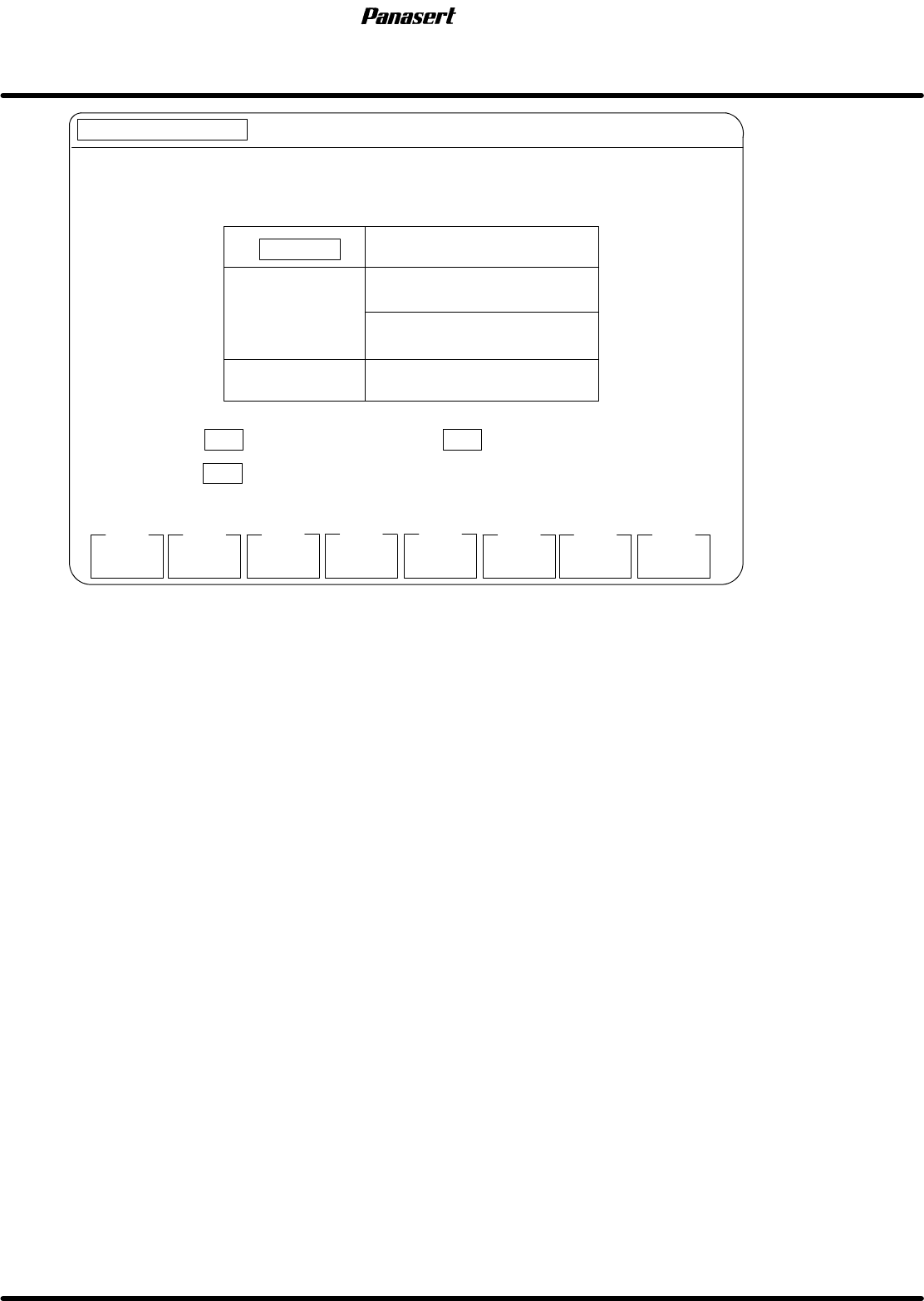
Figure 6.7−14−Recognition service screen
Parameter explanation
CAMERA
· This is a designation of which camera is used.
F1 : PCB camera is used.
F2 : Screen camera is used.
F4 : Display mode is set.
F7 : The light is exchanged.
F8 : The screen returns to the upper level.
SPF
6.7 Secret Screen Service Functions (CONFIDENTIAL)
SERVICE MANUAL
6.7−16
D54SEC−85−080−A0
MANUAL : 1BLOCK
<<MACHINE INITIAL SETTING>> XXXX−XX−XX XX:XX
F1
F2
F3 F4 F5
F6
F7 F8
[RECOGNITION SERVICE]
COMPLETE
ORIGINAL
DISP
2−LEVEL
DISPLAY
F1
PCB CAMERA
F2
DISPLAY MODE
F4
ORIGINAL DISP
POSITIVE
RING
LIGHT TYPE
CAMERA
F3
POS/NEG
DISPLAY
CAMERA
SELECT
LIGHT
SELECT
TO POS / NEG DISPLAY
TO SELECT THE CAMERA
PRESS TO ORIGINAL DISP, TO BINARY LEVEL DISP
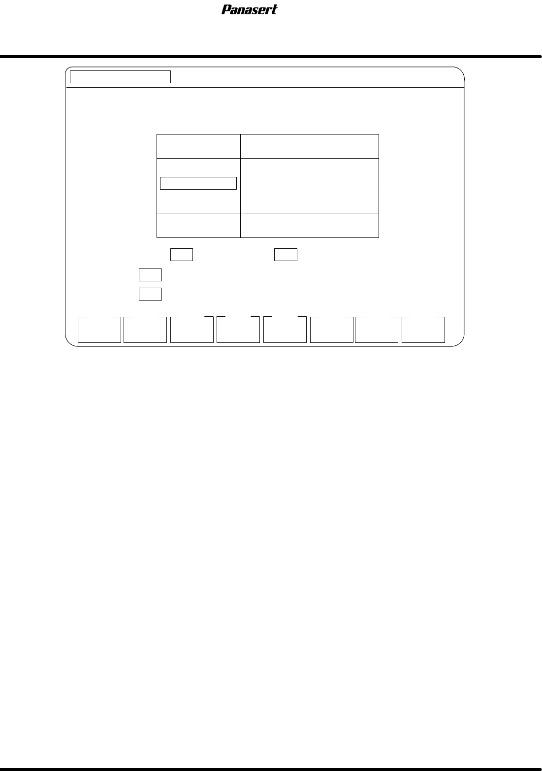
Figure 6.7−15−Recognition service screen
Parameter explanation
DISPLAY MODE
· Select the display mode.
F1 : Original display is used.
F2 : Binary level display is used.
F3 : Positive / Negative display is used.
F4 : Camera selection is executed.
F7 : The light is exchanged.
F8 : The screen returns to the upper level.
6.7 Secret Screen Service Functions (CONFIDENTIAL)
SERVICE MANUAL
SPF
6.7−17
D54SEC−85−080−A0
MANUAL : 1BLOCK
<<MACHINE INITIAL SETTING>>
XXXX−XX−XX XX : XX
F1
F2
F3 F4 F5
F6
F7 F8
[RECOGNITION SERVICE]
COMPLETE
X AXIS
Y AXIS
F1
PCB CAMERA
F2
RING
LIGHT TYPE
CAMERA
LIGHT
SELECT
MOVE A POINTER WHERE YOU WANT TO DISPLAY BRIGHTNESS USING
PRESS TO X−AXIS, TO Y−AXIS.
POINTER COORDINATE X : 256
Y : 240
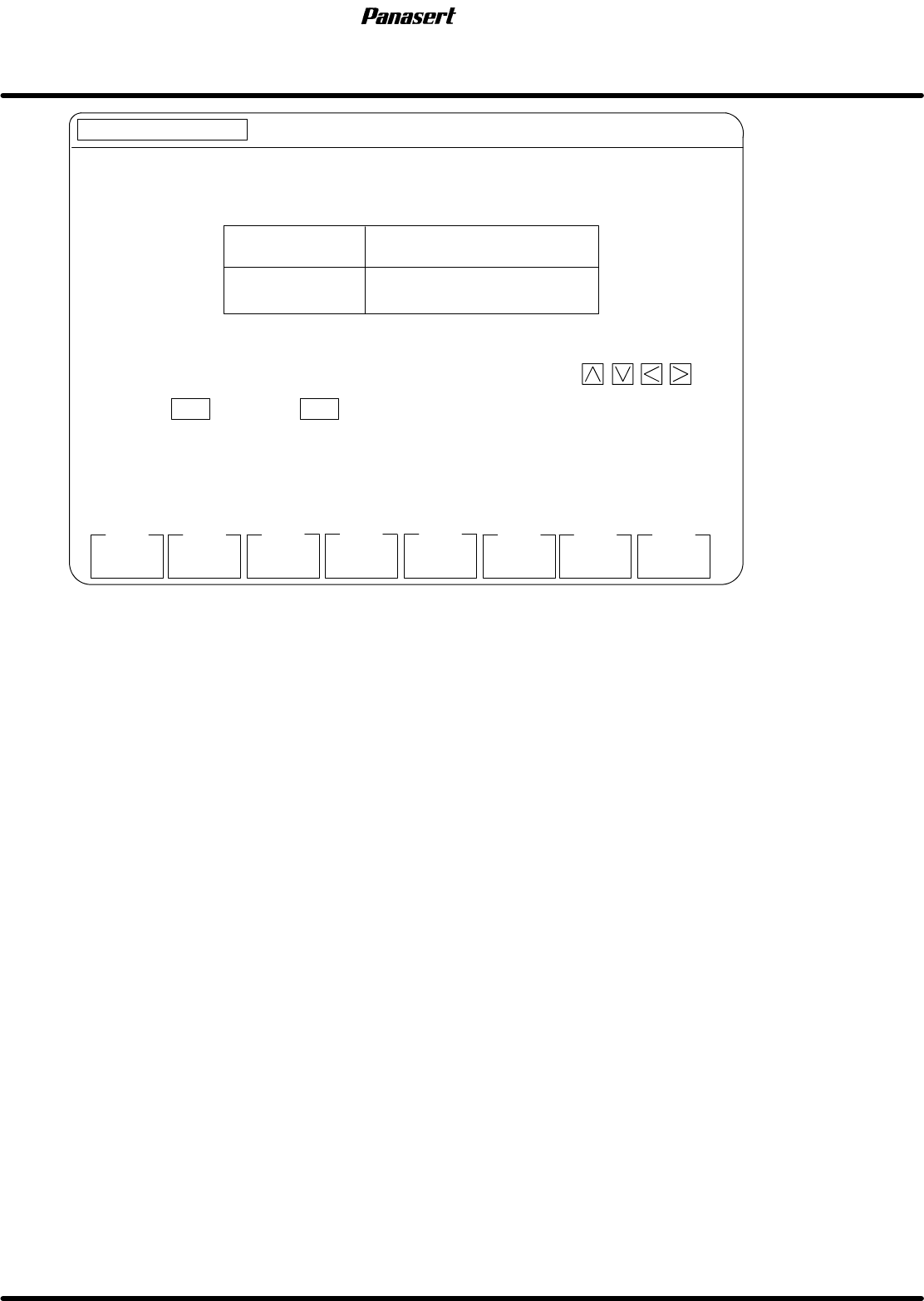
Figure 6.7−16−Recognition service screen
Parameter explanation
· This is a designation of where to display the brightness distribution.
F1 : Brightness distribution of X axis is appears.
F2 : Brightness distribution of Y axis is appears.
F7 : The light is exchanged.
F8 : The screen returns to the upper level.