SPF维修.pdf - 第27页
SPF 2.1 Installation Procedure SERVICE MANUAL 2.1−2 D54SEC−1 1−040−C0 2.1.2 Leveling Machine Leveling machine 1. Remove the fixed bracket for transfer . Fixed bracket for transfer Cleaner unit Main body frame 2. Set mach…
2.1 Installation Procedure
SERVICE MANUAL
SPF
2.1−1
D54SEC−11−040−C0
2.1 Installation Procedure
D54SEC−11−040−C0
Sentence No.
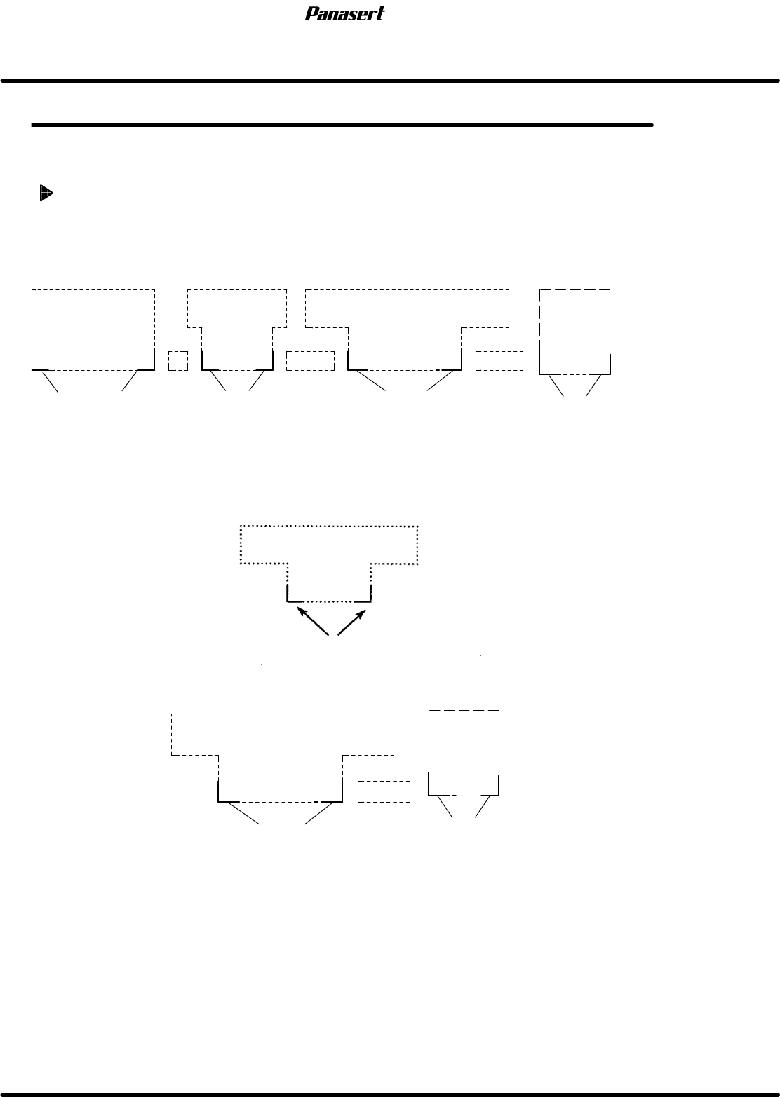
2.1.1 Installation Position
Installation position
1. Decide machine installation position from layout diagram. (CAD diagram, etc.)
2. Mark the reference points of each machine on the floor with a maker pen, etc.
=HINT=
In most cases the machine front corners are used as reference points.
REF−G1
MSF
MSR
Reference point
*C−CON
Reference point
Reference point
C−CON
C−CON
Reference point
SPF
*C−CON are connection conveyors which stand between machines.
3. Install the main body of each machine temporarily at reference point. (Except for C-CON, etc.)
4. In the case of chip mounting line, the installation should start from the heaviest machine.
(MSR, etc.).
Reference point
MSR
5. Install SPF based on the heaviest machine (MSR) as reference.
MSR
C−CON
Reference point
Reference point
SPF
SPF
2.1 Installation Procedure
SERVICE MANUAL
2.1−2
D54SEC−11−040−C0
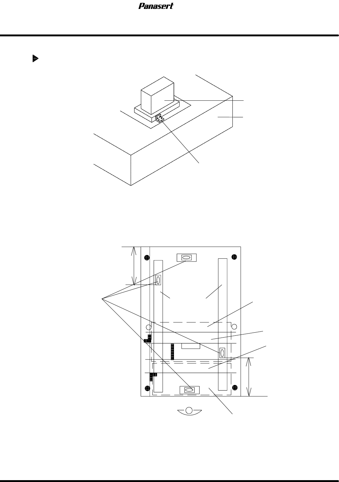
2.1.2 Leveling Machine
Leveling machine
1. Remove the fixed bracket for transfer.
Fixed bracket for transfer
Cleaner unit
Main body frame
2. Set machine main body accurately on the reference points.
3. Remove fixtures (for transportation) of SY, SCR axes (stage Y, q axes), SQ axis (squeegee X axis),
CX, CY axes (camera X, Y axes), CL axis (cleaner Y axis) and stage fixture, squeegee fixtures and
camera Y axis fixtures.
4. Move the stage to center of machine main body.
5. Allow the 2 center legs of the main body to float and adjust the level of the machine using the 4 corner
legs. (Fig. 1)
Levels
Stage Y axis
LM guides
Stage
Cleaner
Camera
Squeegee
350mm
450mm
(Fig. 1)
6. Adjust the 4 legs to level the machine, and fasten with locknut.
=Specification=
Height : 915 ± 5mm

2.1 Installation Procedure
SERVICE MANUAL
SPF
2.1−3
D54SEC−11−040−C0
7. Place the levels in the designated positions on the machine.
=REMARKS=
Make sure that the levels are calibrated.
8. Adjust all other legs, and check that the machine is still leveled.
9. Tighten all legs with locknuts and check that machine is still leveled. (Check that there are no floating
legs.)
2.1.3 Accessories, Power Supply, Air Attachments
Accessories, power supply, air attachments
1. Attach accessories (camera monitor, sub control panel, signal tower, etc.).
2. Connect the air hose to the machine body at the primary side and check the air pressure with main
regulator unit.
=Specification=
Air pressure : 0.49 MPa ( 5 kgf/cm
2
)
=REMARKS=
Remove the oil, dirt, etc. from inside of pneumatic tubing before connecting it.
3. Connect the power supply to the machine transformer at the primary side.
=Specification=
Voltage : Within AC 100 V ± 5 % (1−phase)
Within AC 200 V ± 5 % (3−phase)
4. Check the ground.
=REMARKS=
Make sure that the main breaker at the primary side turn [OFF] when-3−phase is changed the
phase.