SPF维修.pdf - 第50页
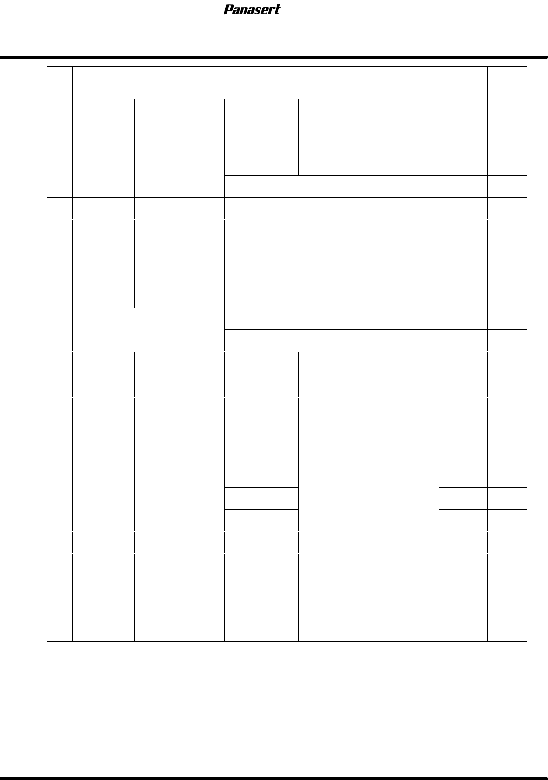
4.1 Adjustment Check List SERVICE MANUAL SPF 4.1−5 D54SEC−83−010−B0 No. Adjustment Item Check Refere nce T ransfer belt tension Wearing and cleaning of transfer belt Loader Clearance between loader rail and stage rail 5.…

SPF
4.1 Adjustment Check List
SERVICE MANUAL
4.1−4
D54SEC−83−010−B0
No.
Adjustment Item Check
Refere
nce
Vertical movement noise,
looseness and rattle, etc.
PCB support plate
Coplanarity
(0°)
Within 0.1mm
Height to
stage rail
upper face
55.9±0.05mm
Positioning unit
automatic width
control
Clearance
between PCB
0.6to1.0mm
4 Stage
Screen holder
Gap between
stage rail
0 to −0.1mm
Screen
holder
Coplanarity Within 0.03mm
Transfer belt tension
Wearing and cleaning of transfer belt
Rail Coplanarity
(0°)
Within 0.1mm
Parallelism
(Fixed rail)
Within 0.2mm

4.1 Adjustment Check List
SERVICE MANUAL
SPF
4.1−5
D54SEC−83−010−B0
No.
Adjustment Item Check
Refere
nce
Transfer belt tension
Wearing and cleaning of transfer belt
Loader
Clearance
between
loader rail and
stage rail
5.0 to 6.0mm
L
oa
d
er
Parallelism
between
loader rail and
stage rail
Within 0.2mm
5
PCB
Gap between
loader rail and
stage rail
Within 0.2mm
5
PCB
transfer
Transfer belt tension
Wearing and cleaning of transfer belt
Unloader
Clearance
between
unloader rail
and stage rail
5.0 to 6.0mm
U
n
l
oa
d
er
Parallelism
between
unloader rail
and stage rail
Within 0.2mm
Gap between
unloader rail
and stage rail
Within −0.2mm
SPF
4.1 Adjustment Check List
SERVICE MANUAL
4.1−6
D54SEC−83−010−B0
No.
Adjustment Item Check
Refere
nce
6 Cleaner Head hei
g
ht
Wet vacuum
(Option)
0 to +0.1mm
6
Cleaner
Head
height
Dry vacuum 0.3 ± 0.1mm
7
T
iming
belt
ST
axis
Tension 96.0 ± 9.8N (9.8±1.0kgf)
7
T
i
m
i
ng
b
e
lt
ST
ax
i
s
Wearing and cleaning of timing belt
8 Camera Camera image Image is clear
MANUAL mode All manual movement using sub control panel
9
O
p
eration
SEMIAUTO mode ZIP positioning
9
Operation
check
AUT
O
mode
PCB transfer
AUT
O
mo
d
e
Recovery movement
10
Functions concerned with NC
NC data input / output
10
Functions
concerned
with
NC
data
Manual data input
Main controll
panel optical loop
(MMI)
Main control
panel
2to12mW
Floating head
optical
loop
5, 6
2
to
12
m
W
op
ti
ca
l
l
oop
(MMC)
7, 8
2
t
o
12
m
W
0, 1
Optical
loop
2, 3
11
Optical
loop
light
intensity
4
intensit
y
8, 9
SC board optical
loo
p
E, F
2to12mW
loop
A, B
6
5
C, D