SPF维修.pdf - 第67页
SPF 4.3 Upper Section Positioning Related Matter SERVICE MANUAL 4.3−2 D54SEC−W1−000−B0 12. Check the ( ± ) limits sensors. =Specification= (+) limit : 6 +0.5 −1.0 0.5mm (−) limit : −6 +1.0 −0.5 0.5mm (−) mechanical stopp…
4.3 Upper Section Positioning Related Matter
SERVICE MANUAL
SPF
4.3−1
D54SEC−W1−000−B0
4.3 Upper Section Positioning Related Matter
D54SEC−W1−000−B0
Sentence No.
4.3.1 SCX Axis (Screen Compensated Axis) Origin Adjustment
Unit No.
SCX Axis (Screen
Compensated Axis) Origin
Adjustment
4.3.4 SCX Axis (Screen
Compensated Axis) Motor
Replacement
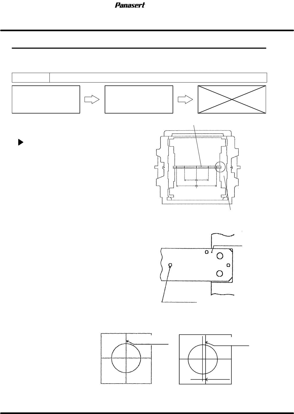
=Preparation=
1. Mark plate jig
SCX axis origin adjustment
1. Turn the power [ON] and return to origin.
2. Fix the mark plate jig to the screen position
compensated table with bolts (4 pcs).
3. Move the CY axis (Camera Y axis) to 490mm.
4. Move the CX axis (Camera X axis) to 165mm for
M size, and move it to 255mm for XL size.
5. Turn “RECOG LIGHT RING” on the sub control
panel [ON].
6. Check that the camera mark matches in the
center of the cross line on the monitor screen.
7. If not, loosen the coupling bolt on the ball screw
side.
8. Rotate the ball screw while watching the monitor
screen, adjust the camera mark position until it
matches in the center of the cross line on the
monitor screen.
9. Tighten the coupling bolt on the ball screw side.
10. Check that the origin sensor detects correctly.
11. Move the sensor dog and check the each limit.
Camera mark
Mark plate jig
Mark plate jig
Screen position compensated table
Camera mark monitor
OK NG
Camera cross line
Camera cross line
Position error
165
165
255
255
SPF
4.3 Upper Section Positioning Related Matter
SERVICE MANUAL
4.3−2
D54SEC−W1−000−B0
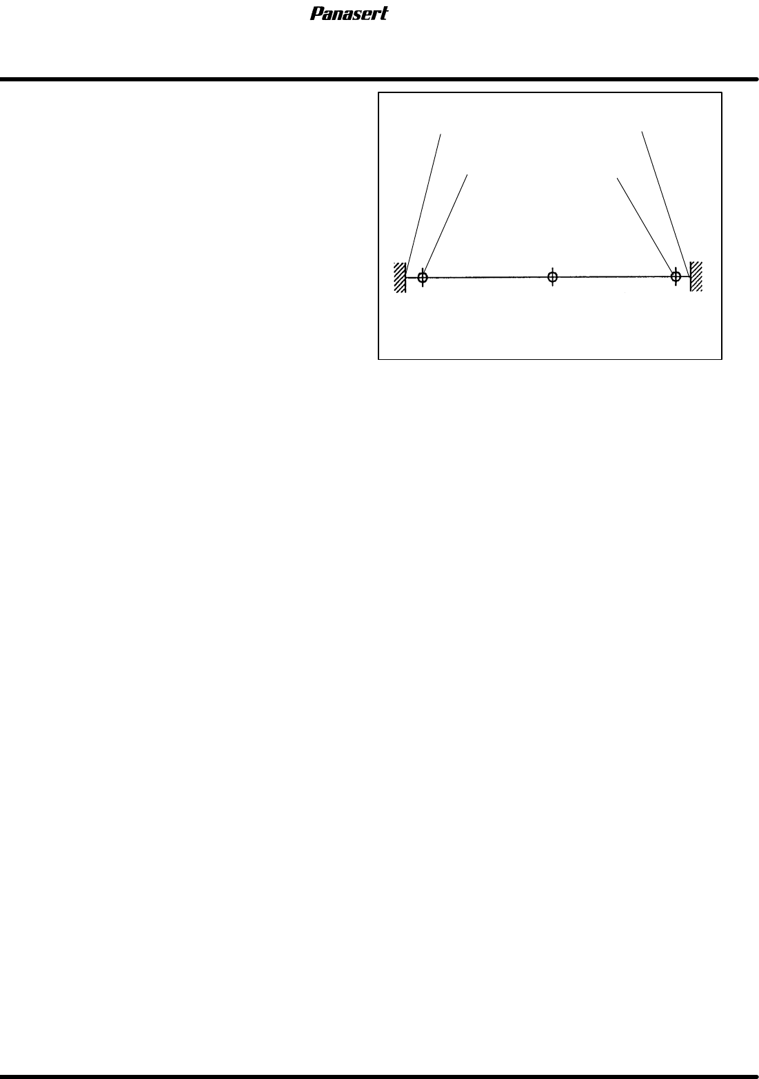
12. Check the (±) limits sensors.
=Specification=
(+) limit : 6
+0.5
−1.0
0.5mm
(−) limit : −6
+1.0
−0.5
0.5mm
(−) mechanical stopper
(−) limit
Origin
(+) mechanical stopper
(+) limit
−7.5
−6
0 7.5
6
Stroke related diagram
4.3 Upper Section Positioning Related Matter
SERVICE MANUAL
SPF
4.3−3
D54SEC−W1−000−B0
4.3.2 SQ Axis (Squeegee Y Axis) Motor Replacement
Unit No. 1080807100,1080807150
SQ Axis (Squeegee Y Axis)
Motor Replacement
4.3.3 SQ Axis (Squeegee Y
Axis) Origin Adjustment
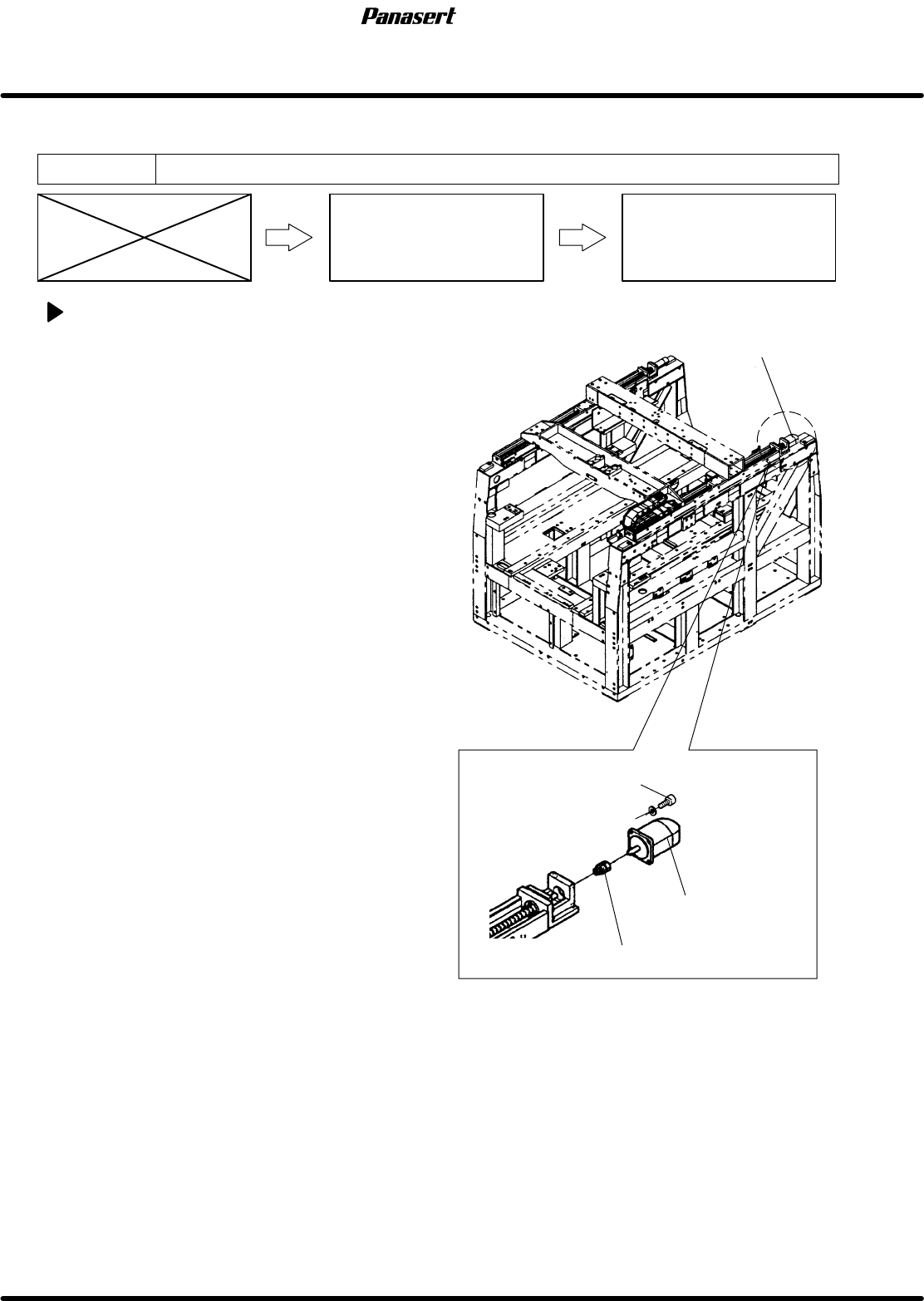
SQ axis motor replacement
1. Turn the power [ON] and return to origin.
2. Turn the power [OFF].
3. Remove the left side cover of the main body.
4. Disconnect the motor connectors.
5. Loosen the N coupling nut on the motor side.
6. Remove the motor bolt and replace the motor.
7. Tighten the motor bolt and N coupling nut on the
motor side.
8. Connect the motor connectors.
SQ axis motor
Motor bolt
N coupling
SQ axis motor