SPF维修.pdf - 第78页
4.5 Upper Section Unit : Others SERVICE MANUAL SPF 4.5−3 D54SEC−W1−V00−B0 16. T ighten the N coupling temporarily with using the spanner . 17. T urn ”SERVO MOTOR” on the main control panel [OFF]. 18. T ighten the N coupl…
SPF
4.5 Upper Section Unit : Others
SERVICE MANUAL
4.5−2
D54SEC−W1−V00−B0
4.5.2 CX Axis Origin Adjustment
Unit No.
CX Axis Origin Adjustment
4.5.4 CX Axis and CY Axis
Squareness Adjustment
=Preparation=
1. Spanner
=CHECK=
Be sure to perform the following
adjustments after completion of the screen
axis origin adjustment and fixed rail guide
parallelism adjustment.
CX axis origin adjustment
1. Turn the power [ON] and return to origin.
2. Move the stage (SY axis) to 150mm.
3. Raise the stage (ST axis) to 26mm.
4. Move the camera (CY axis) to −624.5mm.
=CHECK=
Be sure to check the squeegee (SQ axis) is
at the standby position.
5. Turn “RECOG. LIGHT RING” on the sub
control panel [ON].
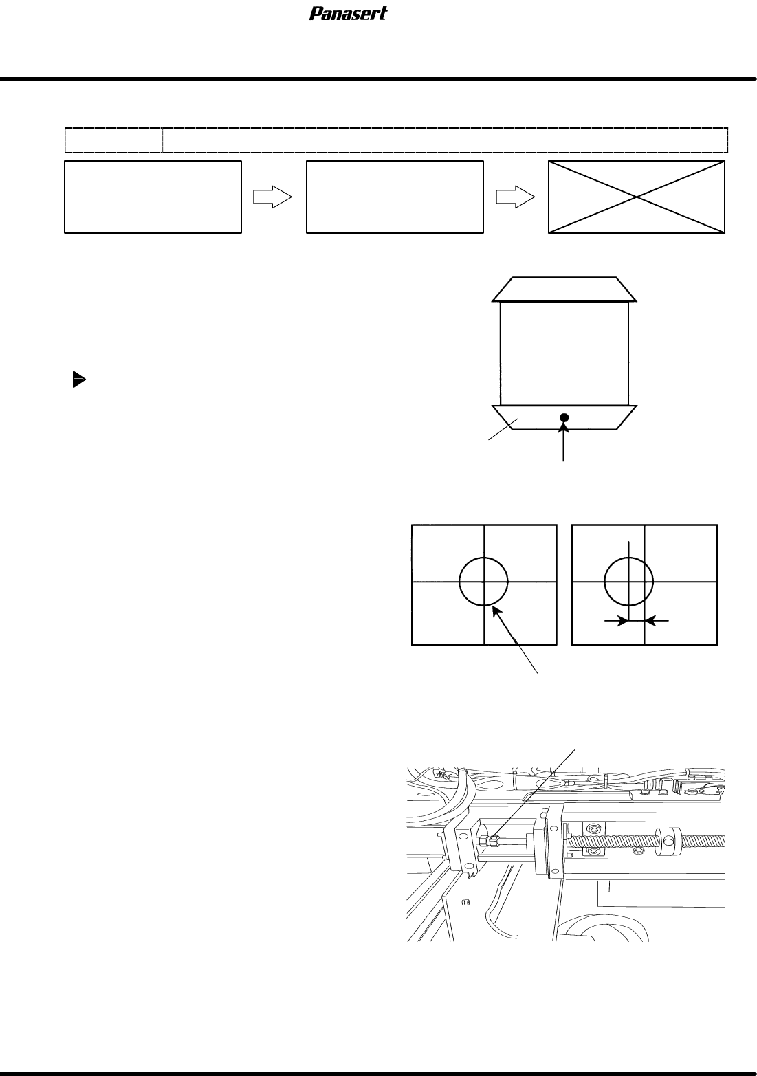
6. Check that the reference mark is at the center of
the cross line on the monitor screen.
7. If not, turn ”SERVO MOTOR” on the main
control panel [OFF].
8. Loosen the N coupling slightly with using the
spanner.
9. Turn ”SERVO MOTOR” on the main control
panel [ON].
10. Return to origin.
11. Select ”MACHINE INITIAL SETTING” ® “F7”
® “SHIFT” ® “S” ® “P” ® “F” on the main
control panel to enter the secret screen.
12. Take a note of the actual gain data.
13. Input the value that decreased gain data.
14. Loosen the N coupling with using the spanner.
=CHECK=
If the gain data is not decreased
beforehand, unusual sound may occur.
15. Rotate the ball screw and move the CX axis until
the reference mark matches with the center of
the screen monitor.
NG
Fixed rail guide
Reference mark
OK
Position error
Coupling
Stage
Reference mark
4.5 Upper Section Unit : Others
SERVICE MANUAL
SPF
4.5−3
D54SEC−W1−V00−B0
16. Tighten the N coupling temporarily with
using the spanner.
17. Turn ”SERVO MOTOR” on the main
control panel [OFF].
18. Tighten the N coupling with using the
spanner.
19. Turn ”SERVO MOTOR” on the main
control panel [ON].
20. Return to origin and check the position
again.
21. Return the changed gain data.
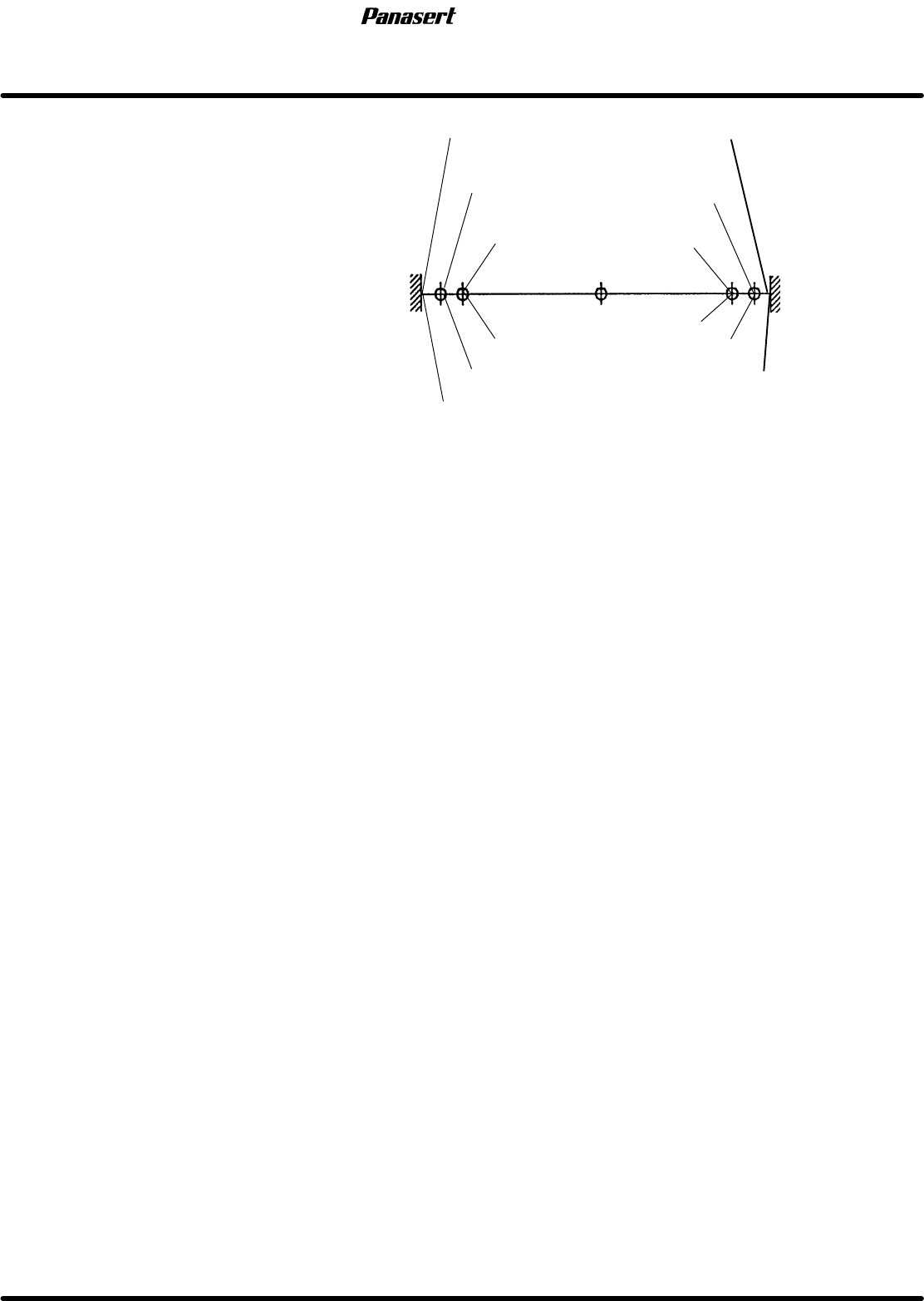
22. Check the limits.
=CHECK=
(−) limit : 256±0.5mm
(+) limit : 282± 0.5mm
(−) mechanical stopper
(−) limit
(−) safety limit
(+) mechanical stopper
(+) limit
(+) safety limit
Origin
−260
0
Stroke related diagram
−258
−256
282
284
286
SPF
4.5 Upper Section Unit : Others
SERVICE MANUAL
4.5−4
D54SEC−W1−V00−B0
4.5.3 CY Axis Origin Adjustment
Unit No.
CY Axis Origin Adjustment
4.5.4 CX Axis and CY Axis
Squareness Adjustment
=Preparation=
1. Spanner
2. Mark plate jig
CY axis origin adjustment
1. Turn the power [ON] and return to origin.
2. Move the camera (CY axis) to −490mm.
3. Move the camera (CX axis) to 0mm.
=CHECK=
Be sure to check the squeegee (SQ axis) is
at the standby position.
4. Turn “RECOG. LIGHT RING” on the sub
control panel [ON].
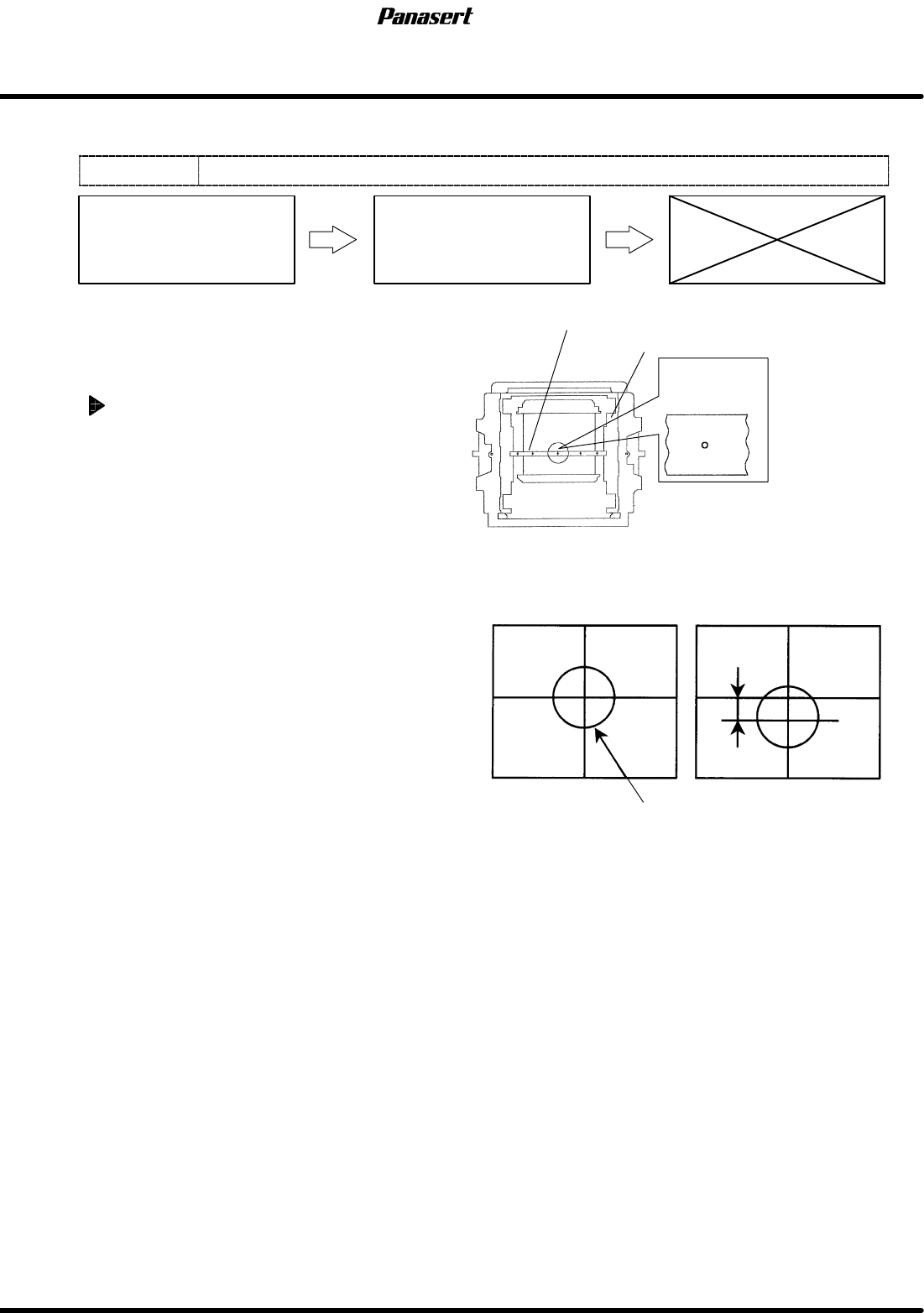
5. Check that the camera mark is at the center of
the cross line on the monitor screen.
6. If not, turn ”SERVO MOTOR” on the main
control panel [OFF].
7. Loosen the N coupling slightly with using the
spanner.
8. Turn ”SERVO MOTOR” on the main control
panel [ON].
9. Return to origin.
10. Select ”MACHINE INITIAL SETTING” ® “F7”
® “SHIFT” ® “S” ® “P” ® “F” on the main
control panel to enter the secret screen.
11. Take a note of the actual gain data.
12. Input the value that decreased gain data.
13. Loosen the N coupling with using the spanner.
=CHECK=
If the gain data is not decreased
beforehand, unusual sound may occur.
14. Rotate the ball screw and move the CY axis until
the camera mark matches with the center of the
screen monitor.
15. Tighten the N coupling temporarily with using
the spanner.
16. Turn ”SERVO MOTOR” on the main control
panel [OFF].
Camera mark
Mark plate jig
Camera mark on the monitor screen
Screen position correction table
OK
Camera mark
Position error
NG