SPF维修.pdf - 第80页
4.5 Upper Section Unit : Others SERVICE MANUAL SPF 4.5−5 D54SEC−W1−V00−B0 17. T ighten the N coupling with using the spanner . 18. T urn ”SERVO MOTOR” on the main control panel [ON]. 19. Return to origin and check the po…
SPF
4.5 Upper Section Unit : Others
SERVICE MANUAL
4.5−4
D54SEC−W1−V00−B0
4.5.3 CY Axis Origin Adjustment
Unit No.
CY Axis Origin Adjustment
4.5.4 CX Axis and CY Axis
Squareness Adjustment
=Preparation=
1. Spanner
2. Mark plate jig
CY axis origin adjustment
1. Turn the power [ON] and return to origin.
2. Move the camera (CY axis) to −490mm.
3. Move the camera (CX axis) to 0mm.
=CHECK=
Be sure to check the squeegee (SQ axis) is
at the standby position.
4. Turn “RECOG. LIGHT RING” on the sub
control panel [ON].
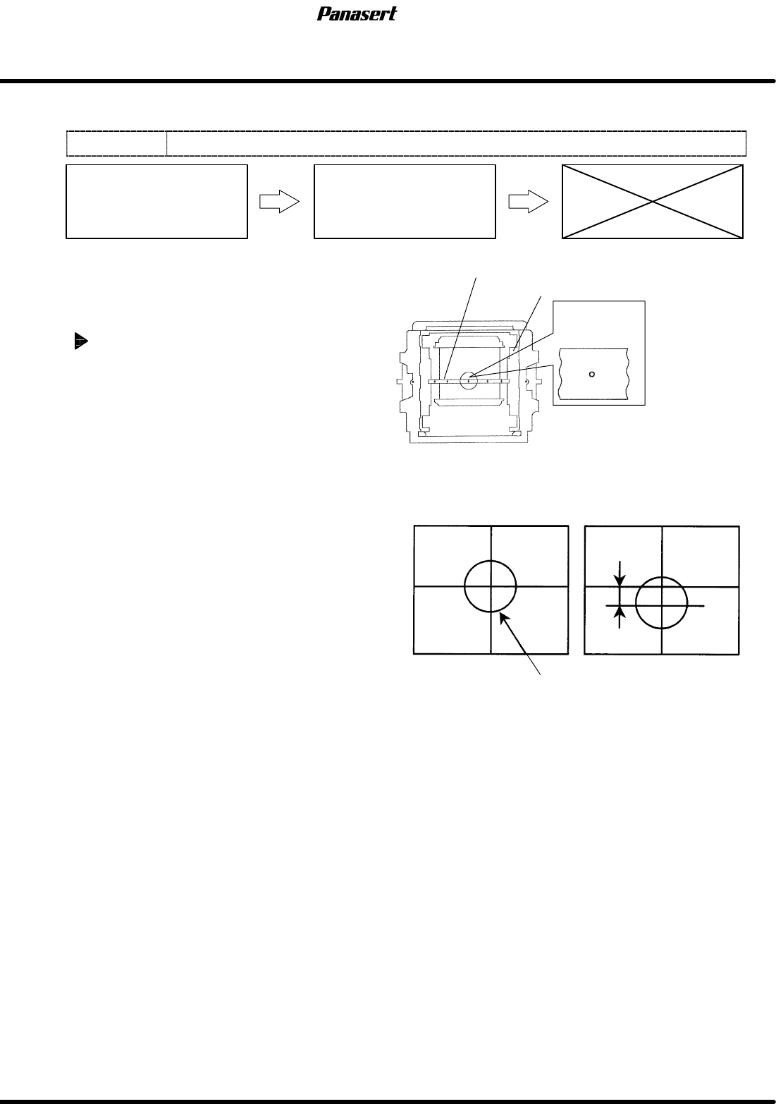
5. Check that the camera mark is at the center of
the cross line on the monitor screen.
6. If not, turn ”SERVO MOTOR” on the main
control panel [OFF].
7. Loosen the N coupling slightly with using the
spanner.
8. Turn ”SERVO MOTOR” on the main control
panel [ON].
9. Return to origin.
10. Select ”MACHINE INITIAL SETTING” ® “F7”
® “SHIFT” ® “S” ® “P” ® “F” on the main
control panel to enter the secret screen.
11. Take a note of the actual gain data.
12. Input the value that decreased gain data.
13. Loosen the N coupling with using the spanner.
=CHECK=
If the gain data is not decreased
beforehand, unusual sound may occur.
14. Rotate the ball screw and move the CY axis until
the camera mark matches with the center of the
screen monitor.
15. Tighten the N coupling temporarily with using
the spanner.
16. Turn ”SERVO MOTOR” on the main control
panel [OFF].
Camera mark
Mark plate jig
Camera mark on the monitor screen
Screen position correction table
OK
Camera mark
Position error
NG
4.5 Upper Section Unit : Others
SERVICE MANUAL
SPF
4.5−5
D54SEC−W1−V00−B0
17. Tighten the N coupling with using the spanner.
18. Turn ”SERVO MOTOR” on the main control
panel [ON].
19. Return to origin and check the position again.
20. Return the changed gain data.
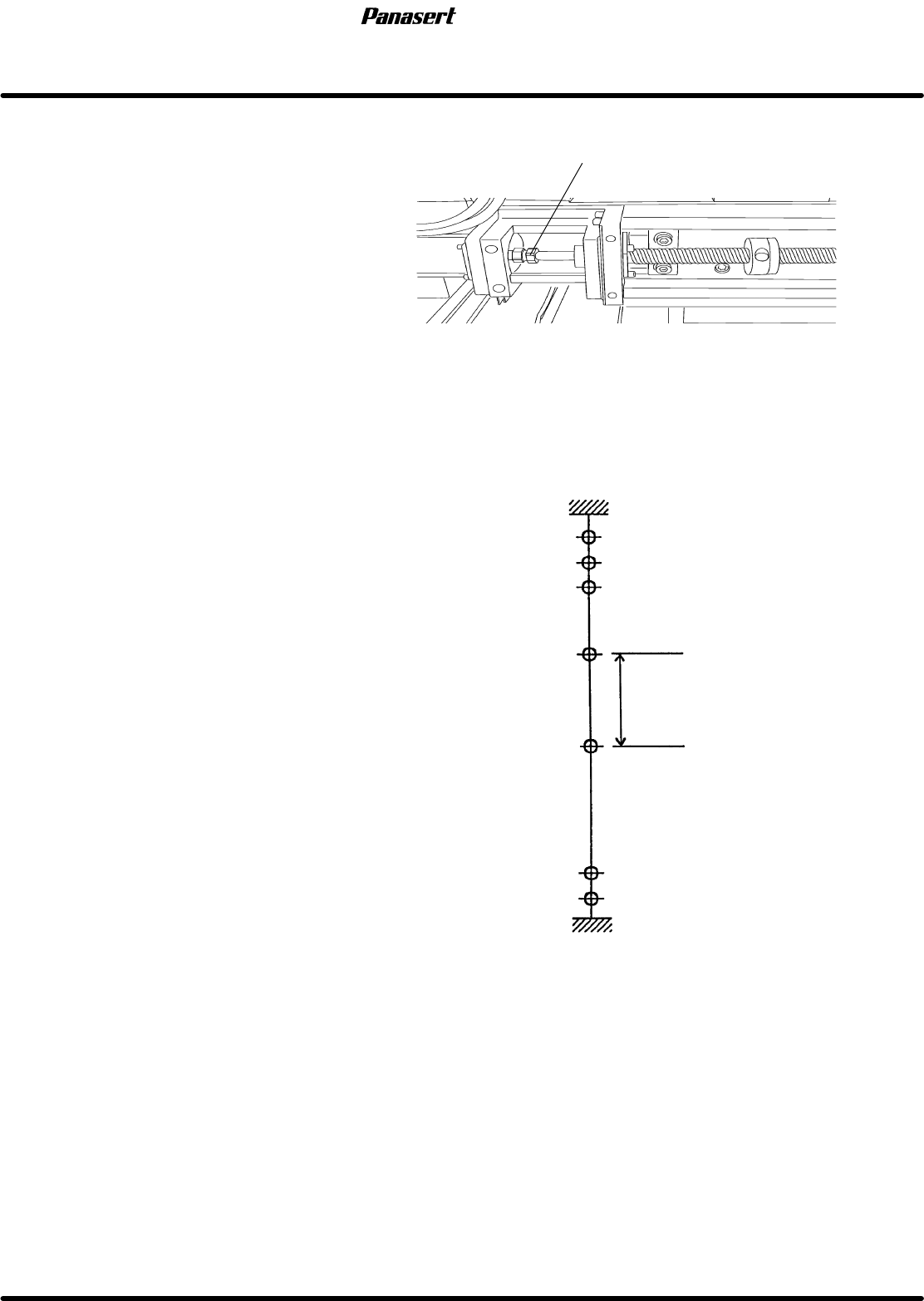
21. Check the limits.
=CHECK=
(+) limit : 1±0.5mm
(−) limit : 721±0.5mm
(−) mechanical stopper
(−) limit
(−) safety limit
(+) mechanical stopper
(+) limit
(+) safety limit
Origin
5
−721
0
Stroke related diagram
In case of SQ axis =−360mm
Coupling
1
3
−86
−723
−725
−200
Camera descent
prohibition range
Coupling
SPF
4.5 Upper Section Unit : Others
SERVICE MANUAL
4.5−6
D54SEC−W1−V00−B0
4.5.4 CX Axis and CY Axis Squareness Adjustment
Unit No.
CX Axis and CY Axis
Squareness Adjustment
4.5.3 CY Axis Origin Adjustment
4.5.2 CX Axis Origin Adjustment
=Preparation=
1. Square
2. Dial gauge
3. Magnet stand
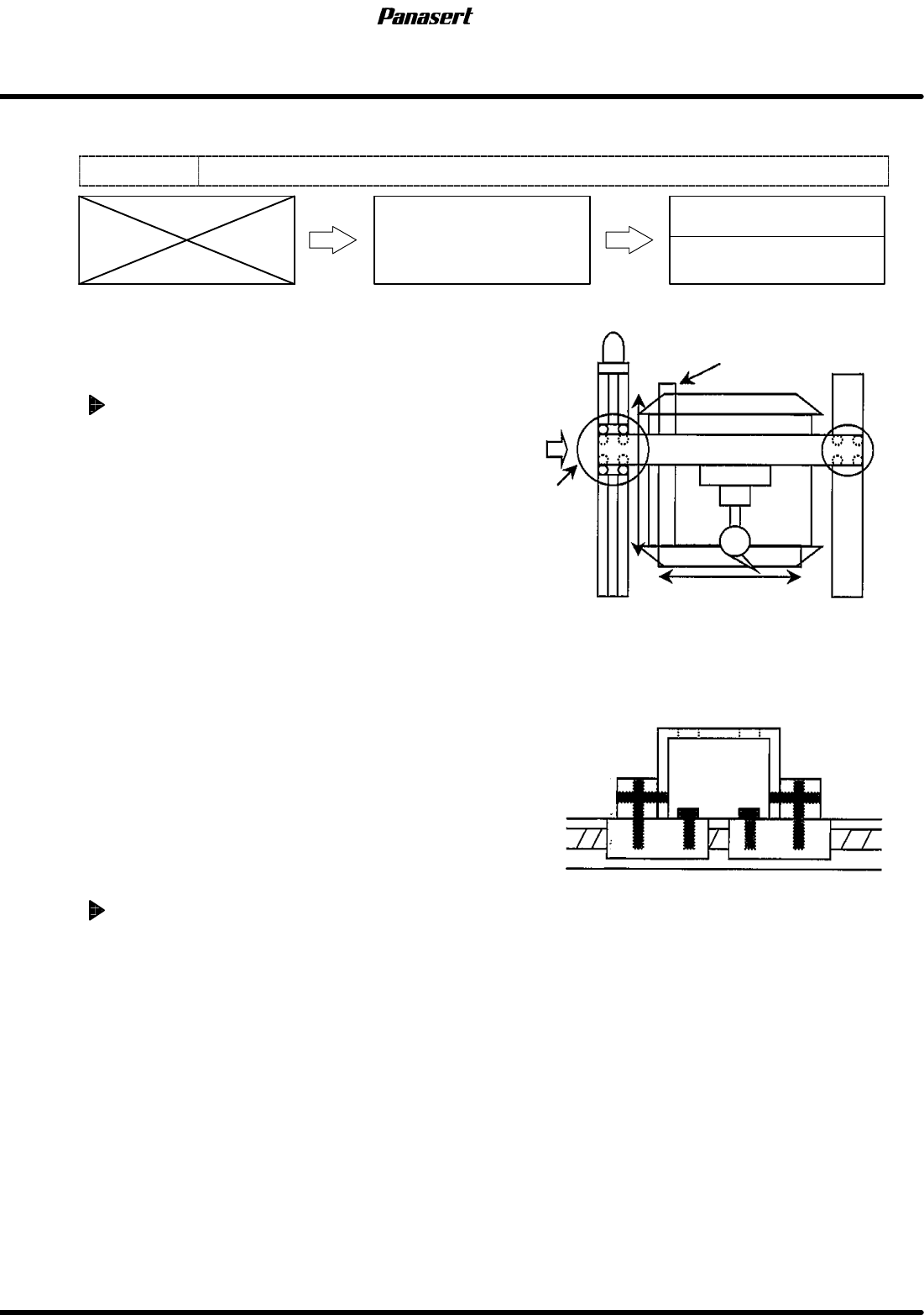
CX axis squareness adjustment
1. Turn the power [ON] and return to origin.
2. Set the square so that it becomes parallel to CY
axis on the table.
=HINT=
Be sure to fix the square with the magnet
stand so that it does not move.
3. Attach the magnet stand to the camera axis
frame.
4. Touch the dial gauge to the point A on the
square.
5. Zero the dial gauge.
6. Check the parallelism of X direction (between A
to B).
=Specification=
Squareness : Within 0.03mm
7. If not within the specification, loosen the joint
bolts of the ball screw.
8. Tighten the one of the joint bolts temporarily.
9. Move the camera axis and tighten the rest of the
joint bolts with checking the parallelism.
10. Check the squareness again.
CY axis squareness adjustment
1. Do the same adjustment as the CX axis.
CY axis
Square
Camera axis
Joint
bolts
Measurement
A
B
0
0
A
Detailed view of A