SPF维修.pdf - 第92页
5.1 AC Servo Gain Adjustment SERVICE MANUAL SPF 5.1−5 D54SEC−84−040−A0 6. The following ’MENU’ screen is displayed on the monitor screen. MANUAL : 1BLOCK <<MACHINE INITIAL SETTING>> XXXX−XX−XX XX : XX F1 F2 F…
SPF
5.1 AC Servo Gain Adjustment
SERVICE MANUAL
5.1−4
D54SEC−84−040−A0
AC servo gain adjustment
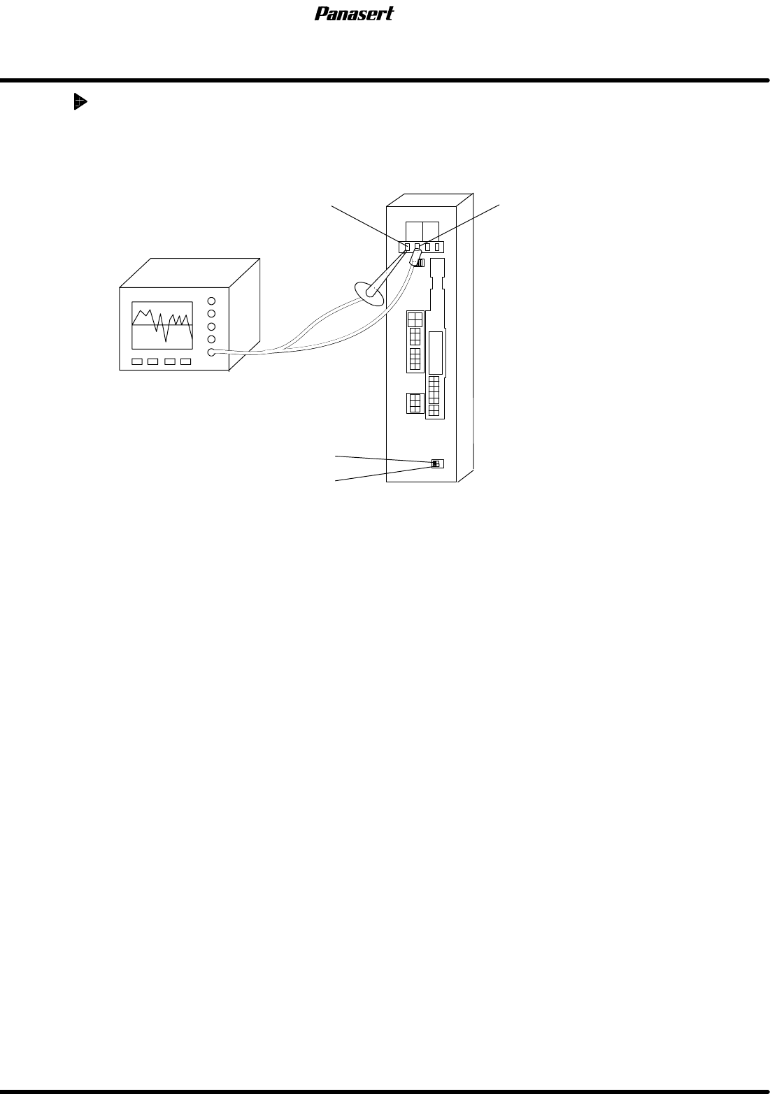
1. Supply the power to the oscilloscope from the other machines except SPF.
2. Attach oscilloscope probe to ’PERM’ and ’GND’ of the motor driver monitor terminal.
PERM GND
ADR2
ADR1
Oscilloscope
3. Select a program.
=HINT=
Any programs can be used under the normal conditions.
4. Execute the program in the aging mode and check the AC servo driver wave and servo motor
condition using the oscilloscope.
5. Select “F1” (MACHINE INITIAL SETTINGS) ® “F7” ® “SHIFT” ® “S” ® “P” ® “SHIFT” ® “F”
from the main control panel.
5.1 AC Servo Gain Adjustment
SERVICE MANUAL
SPF
5.1−5
D54SEC−84−040−A0
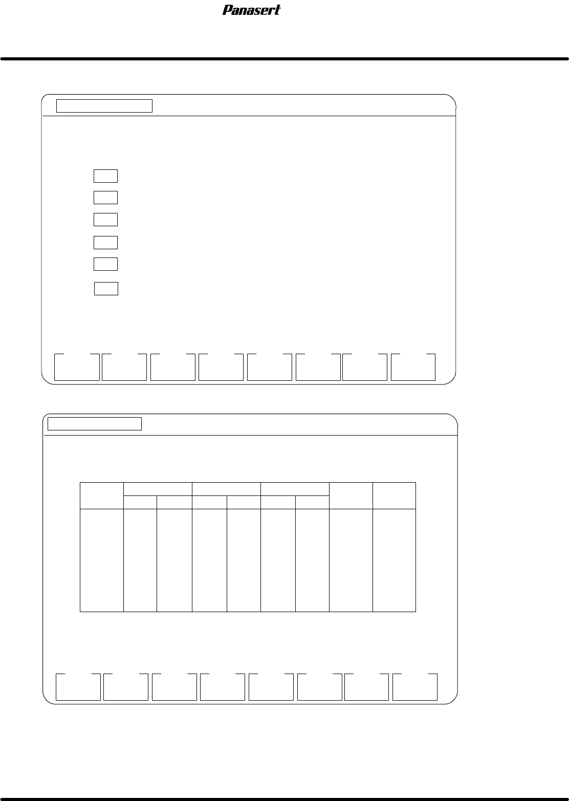
6. The following ’MENU’ screen is displayed on the monitor screen.
MANUAL : 1BLOCK
<<MACHINE INITIAL SETTING>>
XXXX−XX−XX XX : XX
F1
F2 F3 F4 F5 F6
F7 F8
RAM
INITIAL
[MENU]
SYSTEM
PARAM
DRIVER GAIN
SET
OPTION
SWITCH
EXIT
SELECT FUNCTION USING F KEYS.
F 1 INITIALIZES RAM AREA
F2
SETS SYSTEM PARAMETER (RS−232C SETTING, SOFT SW)
F3
SETS SC TIMER
F4
SETS DRIVER GAIN
F5
SETS OPTION SWITCHES
SC TIMER
SET
F6
SETS MACHINE PARAMETERS
MACHIN
PARAM
MORE
FUNCTION
7. Select “F4” (SETS DRIVER GAIN).
MANUAL : 1BLOCK
<<MACHINE INITIAL SETTING>>
XXXX−XX−XX XX:XX
F1
F2 F3 F4 F5 F6
F7 F8
[DRIVER GAIN SETTING]
EXIT
INITIAL
POSITION FEEDB.
FEED
FORWARD
SPEED FEEDBACK
INTEGRAL OF SPD
CHANGE
TIMING
DATA
TRANSFER
CX
CY
ST
SST
SCR
SCX
SY
SQ
9
8
28
12
4
3
8
10
20
13
28
9
2
3
4
9
20
20
21
20
20
5
1
1
0
0
0
0
0
0
0
0
9
8
28
12
5
4
8
10
20
13
28
9
3
4
10
9
0
0
0
0
0
0
0
0
0
0
0
0
0
0
0
0
1st 2nd 1st 2nd 1st 2nd
SPF
5.1 AC Servo Gain Adjustment
SERVICE MANUAL
5.1−6
D54SEC−84−040−A0
8. Check the the difference between the gain setting values and the standard values.
=REFERENCE=
Refer to following table.
AC servo driver standard gain settings
Gain
POSITIONAL
FEEDBACK
SPEED
FEEDBACK
INTEGRAL OF
SPEED
FEED
FOR
W
ARD
CHANGE
TIMING
Gain
1st 2nd 1st 2nd 1st 2nd
FOR
W
ARD
TIMING
CX axis 9 9 20 20 0 20 0 0
CY axis 8 8 13 13 0 20 0 0
ST axis 28 28 28 28 0 21 0 0
SST axis 12 12 9 9 0 20 0 0
SCR axis 5 4 3 2 0 20 0 0
SCX axis 4 3 4 3 0 5 0 0
SY axis 8 8 10 4 0 1 0 0
SQ axis 10 10 9 9 0 1 0 0
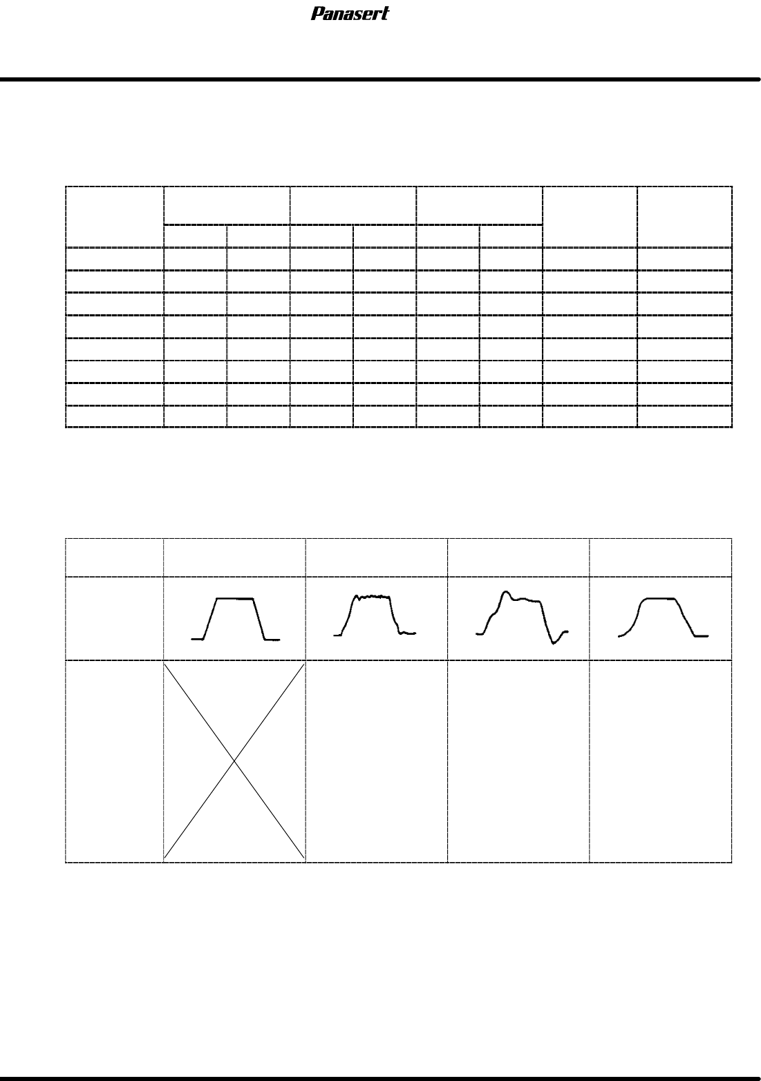
9. Adjust the gain setting values according to following table.
=CHECK=
The values of ’FEED FORWARD’ should be standard value.
Motor
condition
Ideal Noisy
Not smooth
movement
Bad positioning
precision
Wave
Adjustment
procedure
1. Reduce the
speed feedback.
2. Reduce the
integral of speed.
3. Reduce the
positional feedback.
1. Reduce the
positional feedback.
2. Reduce the
speed feedback.
3. Reduce the
integral of speed.
1. Reduce the
positional feedback.
2. Reduce the
speed feedback.
3. Reduce the
integral of speed.
10. Execute the program and check if the problem is solved.
11. If not, try several times.