00192216-01.pdf - 第47页
SIPLACE 80 S-20 / S-23HM/ F4 / F4-6 / F5 2 Retrof itting Instructions for Ceramic S ubstrate Centering Unit (Optional) 04/2000 Issue 2.4 Sequence of Retrofitting 47 .H\WR )LJ A) Direc tion of mov ement for…
2 Retrofitting Instructions for Ceramic Substrate Centering Unit (Optional) SIPLACE 80 S-20 / S-23HM/ F4 / F4-6 / F5
2.4 Sequence of Retrofitting 04/2000 Issue
46
5HPRYLQJWKH3&%+ROGGRZ QV DQG3&%*XLGH5DLOV
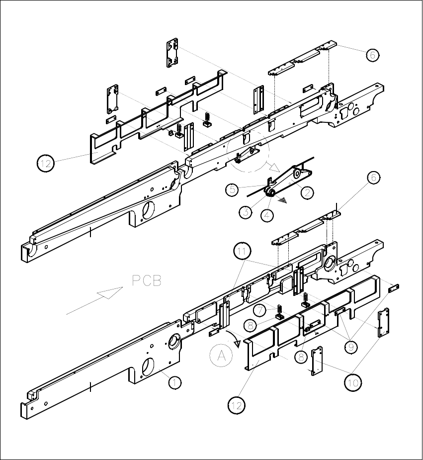
Fig. 2.4.1 Removing the PCB Holddowns and PCB Guide Rails
SIPLACE 80 S-20 / S-23HM/ F4 / F4-6 / F5 2 Retrofitting Instructions for Ceramic Substrate Centering Unit (Optional)
04/2000 Issue 2.4 Sequence of Retrofitting
47
.H\WR)LJ
A) Direction of movement for removal of the holddown device (LH, RH)
8. Conveyor assembly, fixed conveyor side
9. Rocking lever for movable / fixed side: NOT TO REMOVE
10.Set screw M3 x 5
11.Ball bearing (remove to dismantle the lifting table plate)
12.Compression spring on rocking lever
13.PCB guide rails
14.Compression spring for holddown device
15.Retaining bracket (bracket)
16.DU strips (3 units)
17. Guide for holddown
18. Sliding strips (2 units) for holddown device
19. Holddown device (to remove)
Carry out the following steps on the fixed and movable conveyor side:
Å Remove the 3 DU strips (see Fig. 2.4.1 -> 9) and the two guides for the holddown devices (see
Fig. 2.4.1 -> 10 and 11) on the exterior of the conveyor.
To do so, undo and remove the M3 cross-slotted and hexagonal socket head cap screws.
Å Remove the guide rails on both conveyor sides (see Fig. 2.4.1 -> 6).
To do so, undo and remove the socket head cap screws M3.
Å During the subsequent removal of the holddowns make certain that the 2 compression springs
each (see Fig. 2.4.1 -> 7, 8) are not lost:
Å Fold the holddown device to the outside (direction of movement: see Fig. 2.4.1 -> A) and
take it off.
Å During the process, remove the compression spring from the retaining bracket: seeFig.
2.4.1 -> 7 and 8).
2 Retrofitting Instructions for Ceramic Substrate Centering Unit (Optional) SIPLACE 80 S-20 / S-23HM/ F4 / F4-6 / F5
2.4 Sequence of Retrofitting 04/2000 Issue
48
,QVWDOOLQJWKH+ROGGRZQV<&HQWHULQJ8QLWDQG*XLGH3DUWV5HWURILWWLQJ.LW
Å First, adjust the following parts from the retrofitting kit to the substrate size that will be pro-
cessed afterwards, as described in Section 2.4.9:
– Centering unit (slide unit, X-direction)
– Thrust-piece holder
– "Guide rail, RH, assembly"
Å Using 4 countersunk screws M2 x 6, mount the Y-centering unit which consists of the clamping
element with rocker and thrust- piece holder (preassembled) on the rectangular cutout on the
movable conveyor side (see Fig. 2.4.2 -> 3, 4, 5, 6 ).
Å Exchange the compression spring(s) of the pertinent holddown (see Fig. 2.4.1 -> 7), if this is/
they are less than 32 mm long when not subjected to load -> item no. of the compression
spring: see Section 2.3.2.
Å In the reverse order to that described for removal in Section 2.4.3, install the pertinent hold-
down from the retrofitting kit, including the (if necessary, new) compression spring with retain-
ing bracket (support).
Key to Fig. 2.4.2 (RH):
A) Cable proximity switch -> to conversion PCB for PCB conveyor
B) Pneumatic hose -> to the solenoid valve on the back of the compressed air unit
1. Conveyor assembly, movable side
2. Holddown device, movable side *)
3. Clamping element with rocker, installed *) **)
4. Screws to fasten the clamping element: 4 countersunk screws M2 x 6 DIN965 *)
5. Thrust-piece holder (centering in Y-direction) *) **)
6. Screws to fasten the thrust-piece holder **)
7. Actuator for rocker *)
8. Screws to fasten the actuator for the rocker: 2 countersunk screws M2 x 6 *) **)
9. Green plastic rail *)
This is installed instead of ball bearing when the substrates are only centered in the Y-direction.
It is fastened to the thrust-piece holder with 2 countersunk screws M3 x 6 (from the bottom)
each with 2 hex nuts.
10. 2 countersunk screws M3 x 6 (screwed in from the bottom)
*) from retrofit kit
**) already included in the retrofit kit as an installed unit.