00192216-01.pdf - 第50页
2 Retrofitting Instructions for Ceramic Substrate Centering Unit (O ptional) SIPLACE 80 S-20 / S-23HM/ F4 / F4-6 / F5 2.4 Sequence of Retrofitt ing 04/2000 Issue 50 Å Ins tall the (substrate ) "Guide, sh ort" a…
SIPLACE 80 S-20 / S-23HM/ F4 / F4-6 / F5 2 Retrofitting Instructions for Ceramic Substrate Centering Unit (Optional)
04/2000 Issue 2.4 Sequence of Retrofitting
49
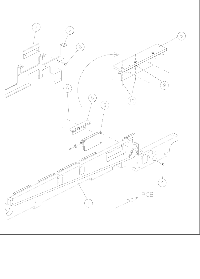
Fig. 2.4.2 Assembly: Clamping Element with Rocker and Thrust-Piece Holder, Rocker Actuator
NOTE:
Do not screw the following substrate guide elements (roller rails) completely tight yet as the align-
ment of the roller rails will have to be adjusted in a later step.

2 Retrofitting Instructions for Ceramic Substrate Centering Unit (Optional) SIPLACE 80 S-20 / S-23HM/ F4 / F4-6 / F5
2.4 Sequence of Retrofitting 04/2000 Issue
50
Å Install the (substrate) "Guide, short" and the (substrate) rail on the movable conveyor side (see
Fig. 2.4.3 -> 7, 8, 9):
-> Use the 2 socket hex head cap screws M3 x 8 previously removed to do so.
Å Install the (substrate) "Guide rail, RH" on the stationary conveyor side (see Fig. 2.4.3):
-> Use the 4 socket hex head cap screws M3 x 8 previously removed.
NOTE:
The 2 connecting rails included in the retrofit kit for the holddowns are not installed because they
are only required for reinstallation on the PCB centering unit (see Section 2.5).
Retain all of the parts not currently used as well as the 2 connecting rails, PCB guide rails and
disassembled ball bearings with shaft and screws so that they will be available for reinstallation
on the PCB conveyor or in case of a change in the substrate size.
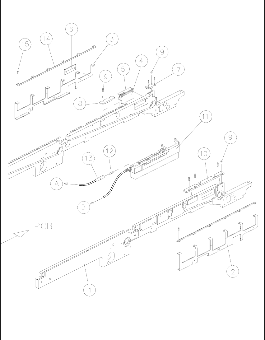
Key to Fig. 2.4.3:
1. Conveyor assembly, fixed side
2. Holddown device for fixed side *)
3. Holddown device for movable side *)
4. Clamping element with rocker, installed *)
5. Thrust-piece holder (centering in Y-direction) *)
6. Rocker actuator *)
7. Guide, short (with rollers) *)
8. Rail (with rollers) *)
9. Fasteners: 2 socket hex head cap screws M3 x 8 *) each
10.Guide rail assembly, RH (long, with rollers) *)
11.Fasteners: 4 socket hex head cap screws M3 x 8 *)
12.inductive proximity switch for ceramic substrate centering unit *)
13.Cable, proximity switch, ceramic substrate centering unit *)
14.PCB holddown bracket (on stationary and movable side) *)
required only for reinstallation on PCB centering unit
15.Fasteners: 6 socket hex head cap screws M3 x 6 *) each
required only for reinstallation on PCB centering unit
*) included in the retrofit kit
SIPLACE 80 S-20 / S-23HM/ F4 / F4-6 / F5 2 Retrofitting Instructions for Ceramic Substrate Centering Unit (Optional)
04/2000 Issue 2.4 Sequence of Retrofitting
51
Fig. 2.4.3 Assembling Holddowns, Guide Rails, Centering Unit; Connecting the Centering Unit