00192216-01.pdf - 第52页
2 Retrofitting Instructions for Ceramic Substrate Centering Unit (O ptional) SIPLACE 80 S-20 / S-23HM/ F4 / F4-6 / F5 2.4 Sequence of Retrofitt ing 04/2000 Issue 52 &RQQHF WLQJWKH6ROHQRLG9 DOY H3RVVLEO\ ,…
SIPLACE 80 S-20 / S-23HM/ F4 / F4-6 / F5 2 Retrofitting Instructions for Ceramic Substrate Centering Unit (Optional)
04/2000 Issue 2.4 Sequence of Retrofitting
51
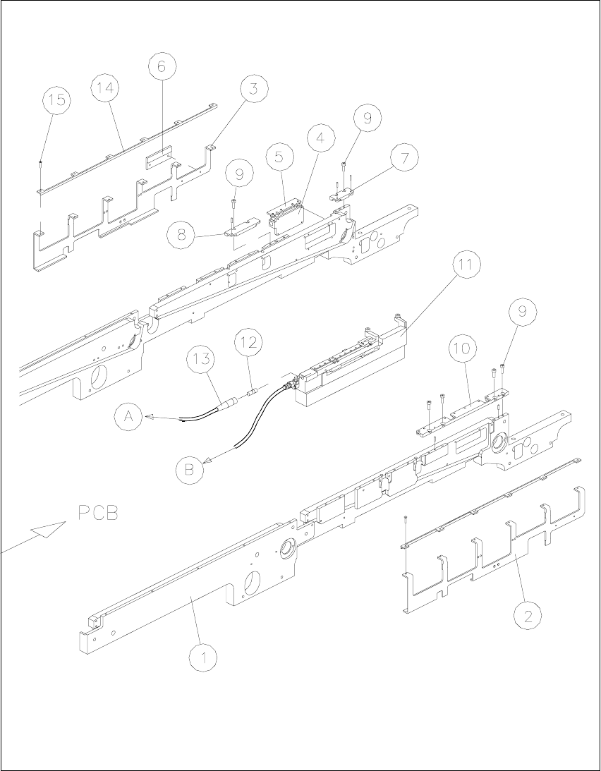
Fig. 2.4.3 Assembling Holddowns, Guide Rails, Centering Unit; Connecting the Centering Unit
2 Retrofitting Instructions for Ceramic Substrate Centering Unit (Optional) SIPLACE 80 S-20 / S-23HM/ F4 / F4-6 / F5
2.4 Sequence of Retrofitting 04/2000 Issue
52
&RQQHFWLQJWKH6ROHQRLG9DOYH3RVVLEO\,QVWDOOLQJQG6ROHQRLG9DOYH
Å The compressed air is already switched off.
On the RH side, loosen the screws fastening the compressed air unit (2 socket hex head cap
screws M 6) and carefully tip the compressed unit forward (see Fig. 2.4.4).
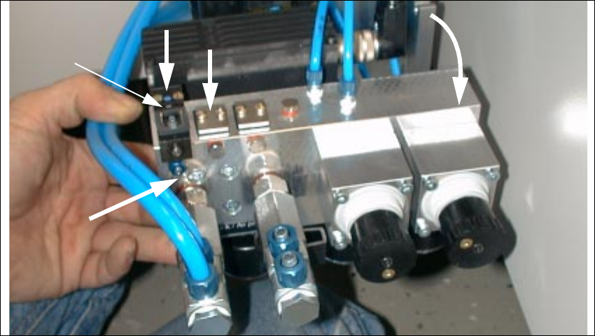
Fig. 2.4.4 Compressed Air Unit: Installing Pneum. Hose and Solenoid Valve Cable, 2nd Solenoid Valve
1. Solenoid valve 1 (included as standard)
2. Module location for solenoid valve 2 (in case of dual conveyor)
3. Connection of pneumatic hose for ceramic substrate centering unit 1
4. Manual actuator for solenoid valve
Å If you install a 2nd ceramic substrate centering unit, you will need a 2nd retrofit kit (see Section
2.3.1). Install the 2nd solenoid valve as follows:
Å Remove the sealing plate next to the existing solenoid valve on the back of the compressed
air unit (2 cross-slotted screws M3: see Fig. 2.4.4 -> 3).
Å Install the sealing plate (see bag in the retrofit kit and the accompanying description) at the
connector that will no longer be in use.
Å On this, install the solenoid valve from the retrofit kit (2 cross-slotted screws M3).
To be certain there are no leaks, check that the screws are tight.
2
1
3
4
SIPLACE 80 S-20 / S-23HM/ F4 / F4-6 / F5 2 Retrofitting Instructions for Ceramic Substrate Centering Unit (Optional)
04/2000 Issue 2.4 Sequence of Retrofitting
53
Å Run the pneumatic hose and the solenoid valve cable for slide unit 1 and - if necessary - 2, as
follows:
Vertically from above into the cutout in the input area (see Fig. 2.4.5) -> Continue further down
into the machine frame; back out on the right next to the maintenance unit.
Å Connect the pertinent pneumatic hose to the threaded hose coupling of allocated solenoid
valve 1 or 2 (see Fig. 2.4.4 -> 3).
In the input area, label the allocation to the specific hose.
– Solenoid valve 1 (LH) -> Connect the ceramic substrate centering unit 1 (conveyor 1)
– Solenoid valve 2 RH) -> Connect the ceramic substrate centering unit 2 (right) -> Connec-
tion of the ceramic substrate centering unit 2 (conveyor 2)
Å Make the plug-and-socket connection to the allocated solenoid valve 1 / 2 as follows:
Å Use the seal suspended from the solenoid valve cable by cable ties and push them over
the connector contacts onto the connector.
Å Use the accompanying cross-slotted screw to fasten the connector in question such that
the seal is not pinched but the connection does not leak.
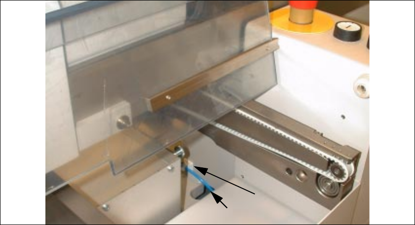
Fig. 2.4.5 Cutout in the Input Area: Running the Pneumatic Hose and Solenoid Valve Cable
Key:
1) Mounting pedestal, adhesive type, and cable ties
2) Pneumatic hose and solenoid valve cable for ceramic substrate centering unit
1