00192216-01.pdf - 第54页
2 Retrofitting Instructions for Ceramic Substrate Centering Unit (O ptional) SIPLACE 80 S-20 / S-23HM/ F4 / F4-6 / F5 2.4 Sequence of Retrofitt ing 04/2000 Issue 54 Å Remo ve grea se from t he ass embly s urfaces for the…
SIPLACE 80 S-20 / S-23HM/ F4 / F4-6 / F5 2 Retrofitting Instructions for Ceramic Substrate Centering Unit (Optional)
04/2000 Issue 2.4 Sequence of Retrofitting
53
Å Run the pneumatic hose and the solenoid valve cable for slide unit 1 and - if necessary - 2, as
follows:
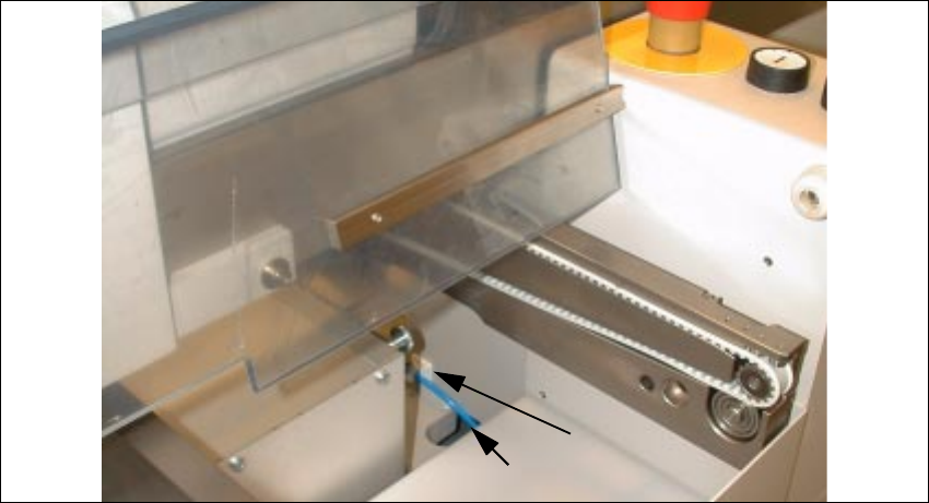
Vertically from above into the cutout in the input area (see Fig. 2.4.5) -> Continue further down
into the machine frame; back out on the right next to the maintenance unit.
Å Connect the pertinent pneumatic hose to the threaded hose coupling of allocated solenoid
valve 1 or 2 (see Fig. 2.4.4 -> 3).
In the input area, label the allocation to the specific hose.
– Solenoid valve 1 (LH) -> Connect the ceramic substrate centering unit 1 (conveyor 1)
– Solenoid valve 2 RH) -> Connect the ceramic substrate centering unit 2 (right) -> Connec-
tion of the ceramic substrate centering unit 2 (conveyor 2)
Å Make the plug-and-socket connection to the allocated solenoid valve 1 / 2 as follows:
Å Use the seal suspended from the solenoid valve cable by cable ties and push them over
the connector contacts onto the connector.
Å Use the accompanying cross-slotted screw to fasten the connector in question such that
the seal is not pinched but the connection does not leak.
Fig. 2.4.5 Cutout in the Input Area: Running the Pneumatic Hose and Solenoid Valve Cable
Key:
1) Mounting pedestal, adhesive type, and cable ties
2) Pneumatic hose and solenoid valve cable for ceramic substrate centering unit
1
2 Retrofitting Instructions for Ceramic Substrate Centering Unit (Optional) SIPLACE 80 S-20 / S-23HM/ F4 / F4-6 / F5
2.4 Sequence of Retrofitting 04/2000 Issue
54
Å Remove grease from the assembly surfaces for the adhesive-type mounting pedestal:
– 1 pedestal in the input area, by machine frame -> see Fig. 2.4.5 -> 1)
– 1 pedestal on the housing of the PCB conveyor drive unit (see Fig. 2.4.6 -> 2) .
Å Install the 2 mounting pedestals (item no.: see Section 2.3.2).
5XQQLQJDQG&RQQHFWLQJ9DOYHDQG3UR[LPLW\6ZLWFK&DEOHV
Å In the PCB conveyor area, remove the cover from the PCB conveyor control and from the cable
pit closest to the stationary conveyor side.
Å Remove the connector sleeves from the solenoid valve cable (see Fig. 2.6.1).
The connector sleeves are intended for installing the option on S-15 and F3.
Å Use the crimp pliers (data for pliers: see Section 2.3.3):
Å Strip the wire ends of the solenoid valve and proximity switch cables to the length required
for the contacts AMPMODU contacts BU 0.12 - 0.56 mm.
Å Attach die AMPMODU contacts BU 0.12 - 0.56 mm to all wire ends.
Å Wire one AMPMODU connector Bu 2 x 3-pin each to proximity switch cable and solenoid
valve cable of specific ceramic substrate centering unit 1 / 2 .
Connector allocation and wire color allocation -> see Fig. 2.6.1 and Fig. 2.6.2.
(on the solenoid valve cable: white corresponds to blue).
Å Insert one AMP LATCH coding pin for each AMPMODU connector (position: see :Key" in
the circuit diagrams, Fig. 2.6.4 and Fig. 2.6.5).
Å Run the solenoid valve cable from the conversion PCB for the PCB conveyor -> Continue in
cable pit in direction of input -> into cutout, to right downward in the input area (into the inside
of the machine frame) -> Out through the large circular opening on the right next to the com-
pressed air unit.
Å Run the cable of the inductive proximity switch from the conversion board of the PCB conveyor
-> Continue in the cable pit -> Continue upward onto the housing of the conveyor drive unit
(see Fig. 2.4.6) in the direction of the output.
SIPLACE 80 S-20 / S-23HM/ F4 / F4-6 / F5 2 Retrofitting Instructions for Ceramic Substrate Centering Unit (Optional)
04/2000 Issue 2.4 Sequence of Retrofitting
55
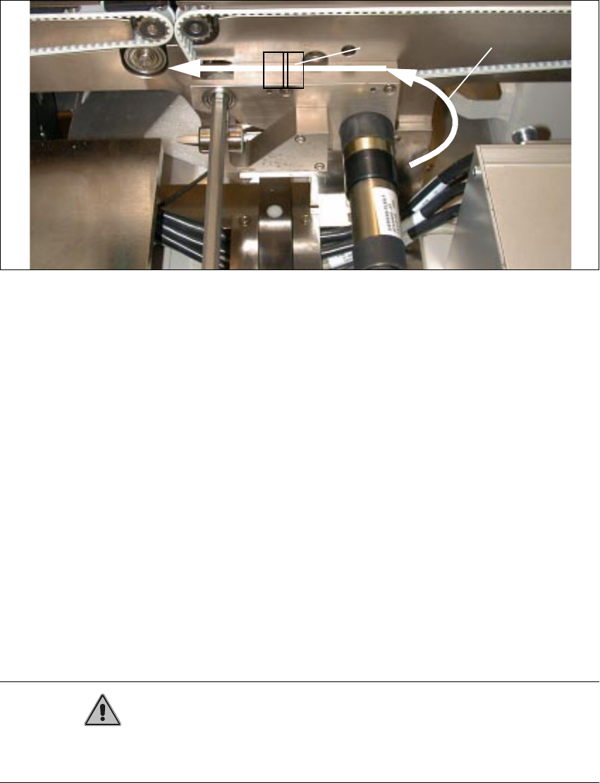
Fig. 2.4.6 Running and Fastening the Proximity Switch Cable and Pneumatic Hose
Key to Fig. 2.4.6:
1. Run proximity switch cable and pneumatic hose
2. Adhesive-type mounting pedestal and cable ties
Å Make the plug-and-socket connection of solenoid valve cable and proximity switch cable to
conversion PCB for PCB conveyor.
Allocation of the plug-and-socket connections (see also circuit diagrams and PCB layout in
Section 2.6):
– Ceramic substrate centering unit 1:
X 46 -> Proximity switch 1
X 48 -> Solenoid valve 1
– Ceramic substrate centering unit 2:
X 47 -> Proximity switch 2
X 49 -> Solenoid valve 2
CAUTION
The cables and the pneumatic hose have to be run such that they are not pinched when the lifting
plate moves up and they do not rub on the corners of the plate.
Å During the subsequent reassembly of the compressed air unit, make certain that you do not
pinch any cable or pneumatic hose.