00192216-01.pdf - 第59页
SIPLACE 80 S-20 / S-23HM/ F4 / F4-6 / F5 2 Retrof itting Instructions for Ceramic S ubstrate Centering Unit (Optional) 04/2000 Issue 2.4 Sequence of Retrofitting 59 6HWWLQJWKH2SHUD WLQJ'LVWDQFHRIWKH3UR[L…
2 Retrofitting Instructions for Ceramic Substrate Centering Unit (Optional) SIPLACE 80 S-20 / S-23HM/ F4 / F4-6 / F5
2.4 Sequence of Retrofitting 04/2000 Issue
58
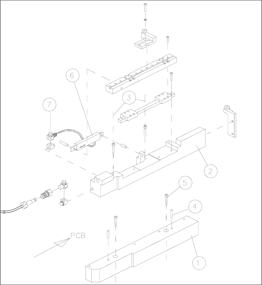
Fig. 2.4.7 Installing the X-Centering Unit on the Lifting Table Plate
1. Bottom part of slide unit
2. Body with slide unit
3. Loosen the screws fastening the body (2 socket hex head cap screws M4)
4. 2 parallel pins 3M5x10 DIN 6325 (for installation on the lifting table plate)
5. 2 socket hex head cap screws M4 x 30 (for installation on the lifting table plate)
6. Flat type compressed air cylinder
7. Throttle valve (opening speed)

SIPLACE 80 S-20 / S-23HM/ F4 / F4-6 / F5 2 Retrofitting Instructions for Ceramic Substrate Centering Unit (Optional)
04/2000 Issue 2.4 Sequence of Retrofitting
59
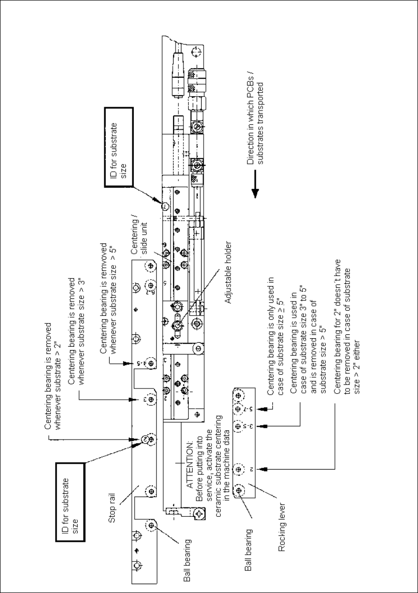
6HWWLQJWKH2SHUD WLQJ'LVWDQFHRIWKH3UR[LPLW\ 6ZLWFK
Å Make certain that the operating surface of the inductive proximity switch is set 0.2 mm back
from the stop surface of the slide unit in the hole.
This precludes the possibility that the proximity switch might serve as a stop during the opening
movement and being damaged as a result.
Å If necessary, correct the position of the proximity switch (grub screw, size 1 Allen wrench).
$GMXVWLQJWRWKH6XEVWUDWH6L]H
To ensure the 3-point contact of the substrate for the centering unit in the Y-direction, the ceramic
substrate centering unit has to be adjusted to the substrate size to be processed afterwards.
The thrust-piece holder and the long guide rail have to be removed to do this (see Fig. 2.4.3 -> 5,
10).
Å Adjust the arrangement of the ball bearings in the long guide rails and in the thrust-piece holder
to the substrate size, as shown in Fig. 2.4.8.
Å If necessary, use a punch (2.5 mm) to drive out the pertinent shaft including the ball bearings
(pressure seating).
NOTE
Carefully save the ball bearings that were removed, including the shaft, so that they will be again
be available for a change made back to a smaller substrate size.
Å If necessary, also adjust the holder on the "slide unit for X-direction) to the required substrate
size (see Fig. 2.4.8).
2 Retrofitting Instructions for Ceramic Substrate Centering Unit (Optional) SIPLACE 80 S-20 / S-23HM/ F4 / F4-6 / F5
2.4 Sequence of Retrofitting 04/2000 Issue
60
Fig. 2.4.8 Adjusting the Substrate Size