00192216-01.pdf - 第64页
2 Retrofitting Instructions for Ceramic Substrate Centering Unit (O ptional) SIPLACE 80 S-20 / S-23HM/ F4 / F4-6 / F5 2.5 Reinstallation on PCB Centering Unit 04/2000 Issue 64 Å On the mo vable co nveyor side , remove : …

SIPLACE 80 S-20 / S-23HM/ F4 / F4-6 / F5 2 Retrofitting Instructions for Ceramic Substrate Centering Unit (Optional)
04/2000 Issue 2.5 Reinstallation on PCB Centering Unit
63
Å Make certain that the pilot LED on the inductive proximity switch lights up when
"Centering unit opened to max.".
In the event of an error, make certain the plug-and-socket connection is securely seated on the
proximity switch. In addition, check the operating distance and, where appropriate, the plug-
and-socket connection on the conversion PCB of the PCB conveyor control.
Å Exit the SITEST program.
Å Start the station software and use the substrate test run (function in the menu "Ceramic sub-
strate centering unit" to make certain that the lifting slide of the centering unit does not bounce
during opening and does not open too slowly, i.e., no error message is output:
- If it opens too slowly, the proximity switch signal turns to 1 but does so too late.
- If it bounces, the proximity switch becomes free again (signal 1 -> 0 -> 1).
Å In the event of an error, correct the setting of the throttle valve for the opening movement ap-
propriately (see Fig. 2.4.7 -> 7).
Å Remove all of the tools, etc., and start the placlement sequence.
5HLQVWDOODWLRQRQ3&%&HQWHULQJ8QLW
5HTXLUHG7RROVDQG$X[LOLDU\0DWHULDOVDQG(TXLS PHQW
– Allen wrenches size 2.5 and 3
– Cross-slotted screwdriver size 1
– Adjustment plate or suitable PCB (see Section 2.3.3)
NOTE:
All of the steps described below are required for final reinstallation.
Only the following steps described below in detail are required for a mere temporary centering of
PCBs:
- Install the holddown brackets on the holddowns,
- Stow the proximity switch cable and pneumatic hose in the cable pit,
- Remove the "Slide unit, X-direction)",
- Slight increase in the Y-clearance of the PCB in the conveyor so that the Y-centering unit
has no effect due to the thrust-piece holder on the swivelling lever (see Fig. 2.4.2).
Å The holddowns from the retrofit kit of the ceramic substrate centering unit are left installed..
Å Install the connecting rails (see Fig. 2.4.3 -> 14, 15) from the retrofit kit of the ceramic substrate
centering unit on the existing holddowns (6 cross-slotted screws M3 for each).
2 Retrofitting Instructions for Ceramic Substrate Centering Unit (Optional) SIPLACE 80 S-20 / S-23HM/ F4 / F4-6 / F5
2.5 Reinstallation on PCB Centering Unit 04/2000 Issue
64
Å On the movable conveyor side, remove:
Å the rocker actuator (see Fig. 2.4.2 -> 6) from the holddown of the stationary conveyor side
(loosen 4 countersunk screws) and
Å the substrate guides (rail, thrust-piece holder and the "Guide, short": see Fig. 2.4.2 -> 5, 7,
8).
Å On the stationary conveyor side, remove the (substrate) "Guide rail, RH" (4 socket hex head
cap screws M3).
Å Place the 2 PCB rails (roller rails) on the stationary and movable conveyor side (Fig. 2.4.1 ->
6) and fasten them with the screws previously removed. Do not tighten the screws completely
yet.
Å Align the PCB guides with the aid of the adjustment plate that you push manually through the
conveyor, in parallel and in alignment inside the conveyor and to the next conveyor. Use
screws to fasten the PCB guides in the adjusted position.
Å Dismantle the "Slide unit, X-direction" from the lifting table (see Fig. 2.4.7). To do this, proceed
in the reverse sequence to that described for installation in Section 2.4.7.
Å Dismantle the lifting table plate (see Section 2.4.2). Loosen the pertinent cable ties and run the
free end of the proximity switch cable and the pneumatic hose back into the cable pit. Re-install
the lifting table plate.
Å 'HDFWLYDWHWKHFHUDPLFVXEVWUDWHFHQWHULQJXQLWLQWKH0$BGDWD
Å Check that the PCB is conveyed satisfactorily in an analog manner to that described in Section
2.4.13 and, if applicable, correct the adjustment of the PCB guide rails.
SIPLACE 80 S-20 / S-23HM/ F4 / F4-6 / F5 2 Retrofitting Instructions for Ceramic Substrate Centering Unit (Optional)
04/2000 Issue 2.6 Appendix: Cables and Circuit Drawings, Conversion PCB
65
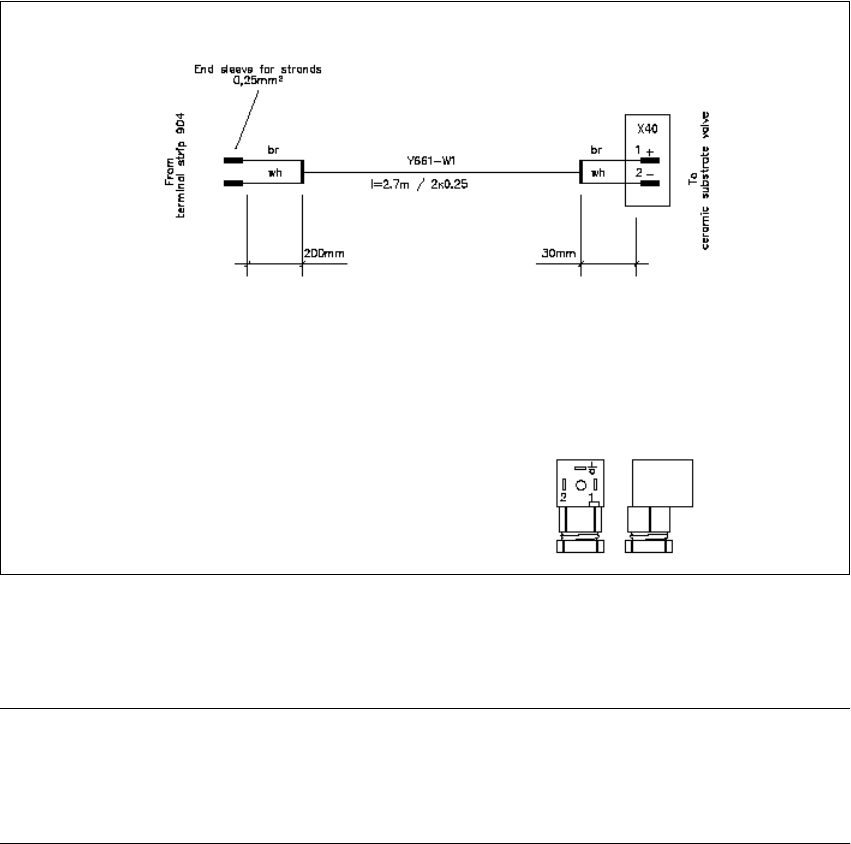
$SSHQGL[ &DEOH VDQG&LUFXLW' UDZLQJV&RQYHU
VLRQ3&%
Fig. 2.6.1 Cable of Solenoid Vavle for SIPLACE 80 F4/F4-6/F5 and S20/S23HM
NOTE:
The connector sleeves of the solenoid valve and proximity switch cable are furnished for
the installation on the SIPLACE S-15 / F3. In all other instances, you must remove them and attach
AMPMODU contacts instead (details: see Section 2.4.5).