WPC an:on SIPLACE SX1:SX2 Montageanleitung : Assembly Instructions.pdf - 第77页
5 Appendix Mo nt ag ea nl ei tu ng / A ss em bl y In st ru ct io ns W PC a n/ on S IP LA CE S X1 /S X2 - 0 3/ 20 25 77 LED status error frames LED status S1.3 S1.4 S1.5 1 error frame OFF OFF OFF 5 error frames/minute ON …
5 Appendix
76 Montageanleitung / Assembly Instructions WPC an/on SIPLACE SX1/SX2 - 03/2025
5.1.2 Setting the DIP Switch on the CAN Switch
► Disconnect the CAN switch from the voltage supply.
► Loosen the two screws fastening the upper section (side with label) and remove this upper sec-
tion.
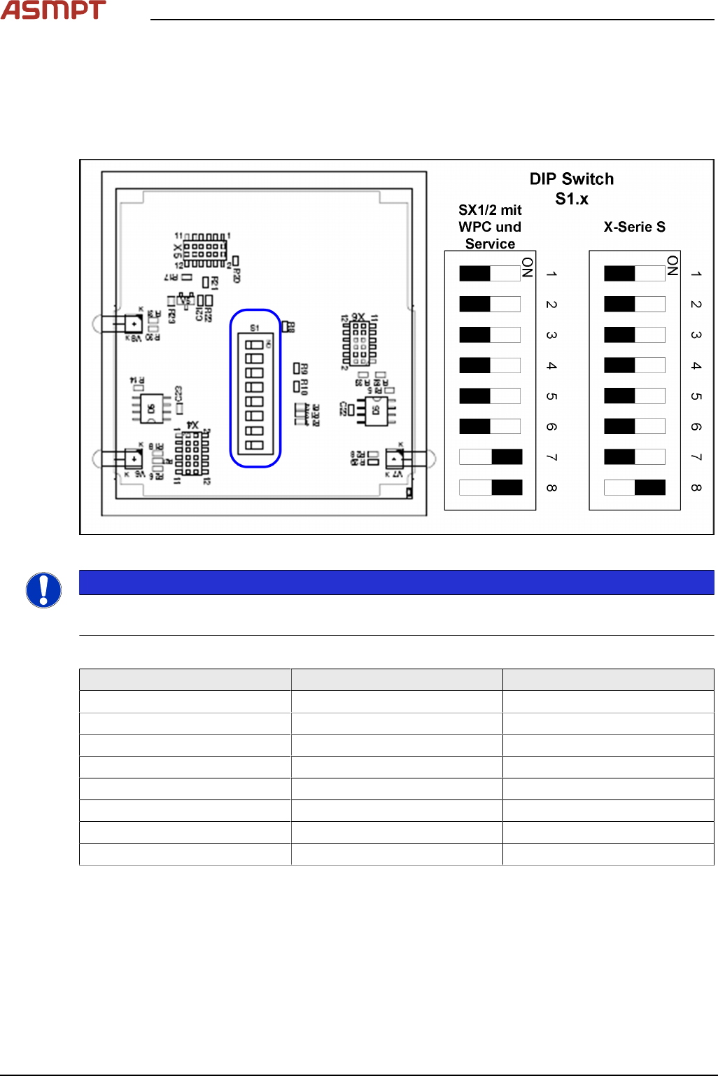
► Set the DIP switches:
Fig.30: Board in CAN switch [03083844-xx]
NOTICE
Default setting
The CAN switch is preset as a default for the SIPLACE X-Series S.
DIP switch S1 in CAN switch [03083844-xx]
DIP switch S1 ON OFF
S1.1 Test mode Normal mode
S1.2 500 kBaud 1 MBaud
S1.3 See table below See table below
S1.4 See table below See table below
S1.5 See table below See table below
S1.6 ASC Test ON ASC Test OFF
S1.7 120 Ohm CAN 1 No terminal resistor
S1.8 120 Ohm CAN 2 No terminal resistor
The DIP switch setting S1.3 to S1.5 is used to configure the display (LED) i.e the number of error
frames needed for the LED to change its status from green to red. The default setting is that the LED
turns red for each error frame received.
5 Appendix
Montageanleitung / Assembly Instructions WPC an/on SIPLACE SX1/SX2 - 03/2025 77
LED status error frames
LED status S1.3 S1.4 S1.5
1 error frame OFF OFF OFF
5 error frames/minute ON OFF OFF
10 error frames/minute OFF ON OFF
10 error frames/hour ON ON OFF
50 error frames/hour OFF OFF ON
100 error frames/hour ON OFF ON
500 error frames/hour OFF ON ON
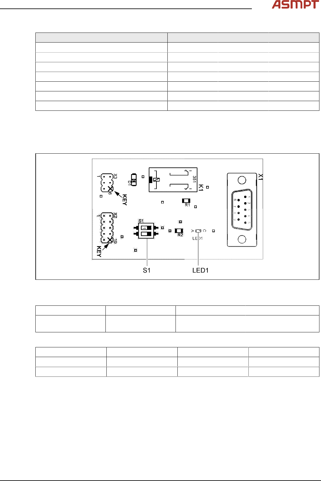
5.1.3 CAN bus terminator for CO table [03046863-xx]
The "CAN bus terminal changeover table" ensures that the CAN bus still works even when a WPC is
fitted. During undocking, a CAN terminating resistor is switched, which maintains the CAN bus function
and communication.
Fig.31: 03046863-01
LED [03046863-01]
LED Color Status Description
LED1 GN ON 24 VDC on connector
X3:4
Switch [03046863-01]
Switch Signal name Location 1 (gantry 1) Location 2 (gantry 2)
S1.1 ADR_0 ON ON
S1.2 ADR_1 ON OFF
5 Appendix
78 Montageanleitung / Assembly Instructions WPC an/on SIPLACE SX1/SX2 - 03/2025
5.1.4 Replacing the Waste Tape Chute
Parts, equipment and tools
Select the appropriate waste tape chute:
Assembly Waste tape chute
Changeover table insert 60 [03059353-xx] Waste tape slide SX1/2 COT60 [03064026-xx]
Changeover table insert 30 [03067206-xx] Waste tape slide SX1/2 COT30 [03073312-xx]
Removal
► Switch off the machine, disconnect it from the power supply and secure it to prevent unauthorized
reactivation.
1.2 "Preparatory work..." [}51]
► Unhook the waste tape chute.
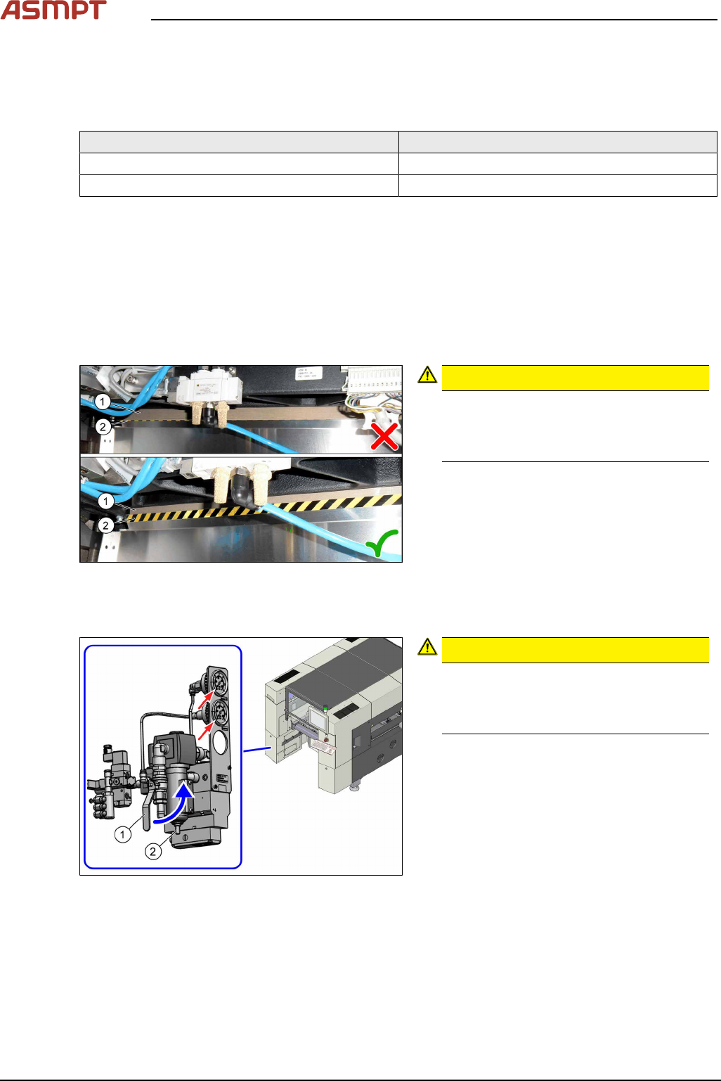
Installation
► Hook the waste tape chute into place.
Fig.32: Plastic strips
CAUTION!
Make sure that the plastic strips(1) are
located behind the plate(2).
The black-yellow hatched label must be
completely visible.
.
5.1.5 Disabling the compressed air supply
Fig.33: Shutting off the compressed air supply
CAUTION!
Switch off the compressed air supply
When working on the pneumatic system,
always switch off the compressed air sup-
ply.
.
► Push the lever (1) for the compressed air
supply upwards until it is positioned hori-
zontally.
► Open the screw (2) on the inlet filter to
vent the system. Hold a cloth underneath
to capture any escaping liquid.
► All pressure gauges must be set to zero.
If you are working on cutters, you will need to vent these as follows: