WPC an:on SIPLACE SX1:SX2 Montageanleitung : Assembly Instructions.pdf - 第59页
3 Setting up and Commissioning Mo nt ag ea nl ei tu ng / A ss em bl y In st ru ct io ns W PC a n/ on S IP LA CE S X1 /S X2 - 0 3/ 20 25 59 3 Setting up and Commissioning When operating the WPC5 on a SX1/SX2 machine, you …

2 Brief description
58 Montageanleitung / Assembly Instructions WPC an/on SIPLACE SX1/SX2 - 03/2025
2.2 Overview of WPC5/6 COT Insert
Fig.8: Overview of the WPC5/6 Insert
1. Docking area for the WPC5/6
2. Docking area for the changeover table
with 30 locations
3. Connections for the component trolley
feed device
4. Installation point for the nozzle changer
5. Feeder control unit
2.3 Scope of Delivery
The following parts are required for the conversion (order separately if necessary):
●
Waffle pack changer WPC5 [00119827-xx]
or
waffle pack changer WPC6 [00119828-xx]
●
Component trolley feed device for WPC5 [03067206-xx]
●
Waste chute COT 30 [03073312-xx]
●
Changeover table SIPLACE SX, 30 feeder slots [00519722-xx]
●
If required, 2x upgrade kits COT-I 30 CAN-Switch 2. WPC [03085518-xx]
These two upgrade kits are required in case of two WPC installations on one machine.
In case of one WPC on one machine no upgrade kit is necessary.
●
Assembly instructions "WPC5 on SX1/SX2" [00196630-xx] (these instructions)
2.4 Tools and Equipment Required
●
Standard tooling
●
recommended
– Fit-up aid complete for COT-Insert P001 [03072616-xx]
– Suitable lifting device (e.g. hand-operated crane)
3 Setting up and Commissioning
Montageanleitung / Assembly Instructions WPC an/on SIPLACE SX1/SX2 - 03/2025 59
3 Setting up and Commissioning
When operating the WPC5 on a SX1/SX2 machine, you need to use a special component trolley feed
device (COT-i30).
First remove the standard component trolley feed device (COT-i60). Then install the special compo-
nent trolley feed device for the WPC5.
3.1 Removing the Standard Component Trolley Feed Device
► Switch off the machine, disconnect it from the power supply and secure it to prevent unauthorized
reactivation.
1.2 "Preparatory work..." [}51]
► Remove the waste tape slide.
► Unplug all connection cables and hoses on the nozzle changer. You may want to mark their posi-
tions, to make clear assignment easier later on.
► Dismantle the nozzle changer.
► Unplug all connection cables and hoses for the insert. These are in sectors 2 and 4, on the right
of the location. You may want to mark their positions, to make clear assignment easier later on.
► Lower the cutter onto the bracket. Proceed as follows:
WARNING
Risk of injury when working near the tape cutter
There are sharp blades inside the tape cutter.
► Do not reach into the tape cutter.
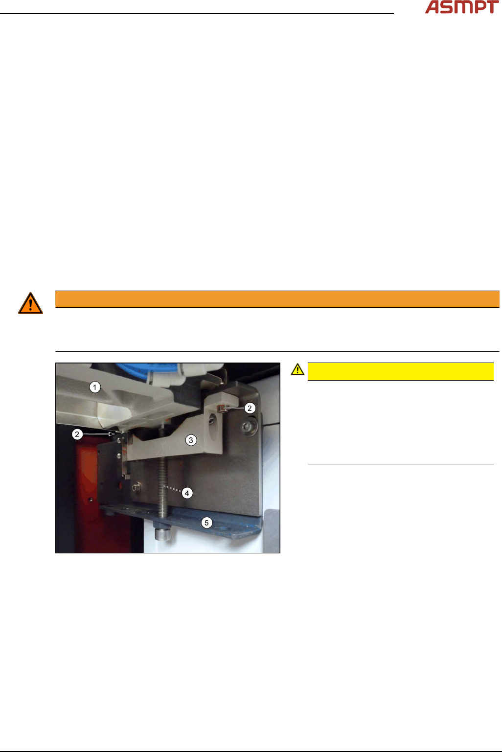
Fig.9: Cutter
CAUTION!
Risk of injury when releasing the fix-
tures!
The cutter (1) is only held by the four
fastening screws (2). If the four fastening
screws are loosened without the cutter
being secured, this will fall down onto the
bracket (5)!
.
► Turn the two supporting screws (4) up to
the top.
► Remove the four screws(2) fastening the
brackets(3) of the cutter and remove
these brackets. The cutter is now resting
on the supporting screws.
► Carefully lower the cutter onto the brack-
ets by slowly and evenly (right and left)
lowering the supporting screws.
3 Setting up and Commissioning
60 Montageanleitung / Assembly Instructions WPC an/on SIPLACE SX1/SX2 - 03/2025
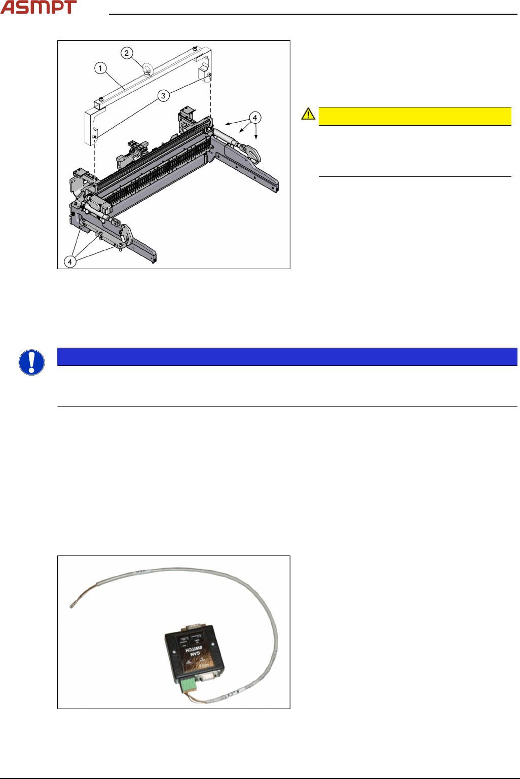
Fig.10: Mounting tool (example of X-Series shown)
1. Mounting tool
2. Eyelet
3. Fastening screws for mounting tool
4. Fastening screws for COT insert
CAUTION!
Heavy machine part!
The COT insert is heavy. To lift it out, you
will need to use the fit-up aid and a suit-
able lifting device.
.
► Attach the mounting tool to the fixtures provided on the COT insert.
► Remove the six screws fastening the COT insert.
► Fix the lifting device to the eyelet of the mounting tool.
NOTICE
Positions
The COT insert can be installed at different positions (inner/outer) in the machine location. Mark the
position of your COT insert, to ensure that this is subsequently returned to its original position.
► Lift the complete COT insert out of the machine and place it on a suitable surface (e.g. four
wooden blocks).
► Make sure that you do not damage any valves, connection cables, hoses etc.
See also
2 1.2 "Preparatory work..." [}51]
3.2 Installation of the CAN switches with two WPCs
Overview
Fig.11: CAN switch with cable
Upgrade Kit COT-I-30 CAN Switch for 2nd
WPC [03085518-xx]
In case of two WPCs operating on one machine
the installation of a CAN switch on each loca-
tion is required.