WPC an:on SIPLACE SX1:SX2 Montageanleitung : Assembly Instructions.pdf - 第62页
3 Setting up and Commissioning 62 Mo nt ag ea nl ei tu ng / A ss em bl y In st ru ct io ns W PC a n/ on S IP LA CE S X1 /S X2 - 0 3/ 20 25 Fig.14: Detailed circuit diagram CAN switch ► Set the DIP switches on the "…
3 Setting up and Commissioning
Montageanleitung / Assembly Instructions WPC an/on SIPLACE SX1/SX2 - 03/2025 61
Installation
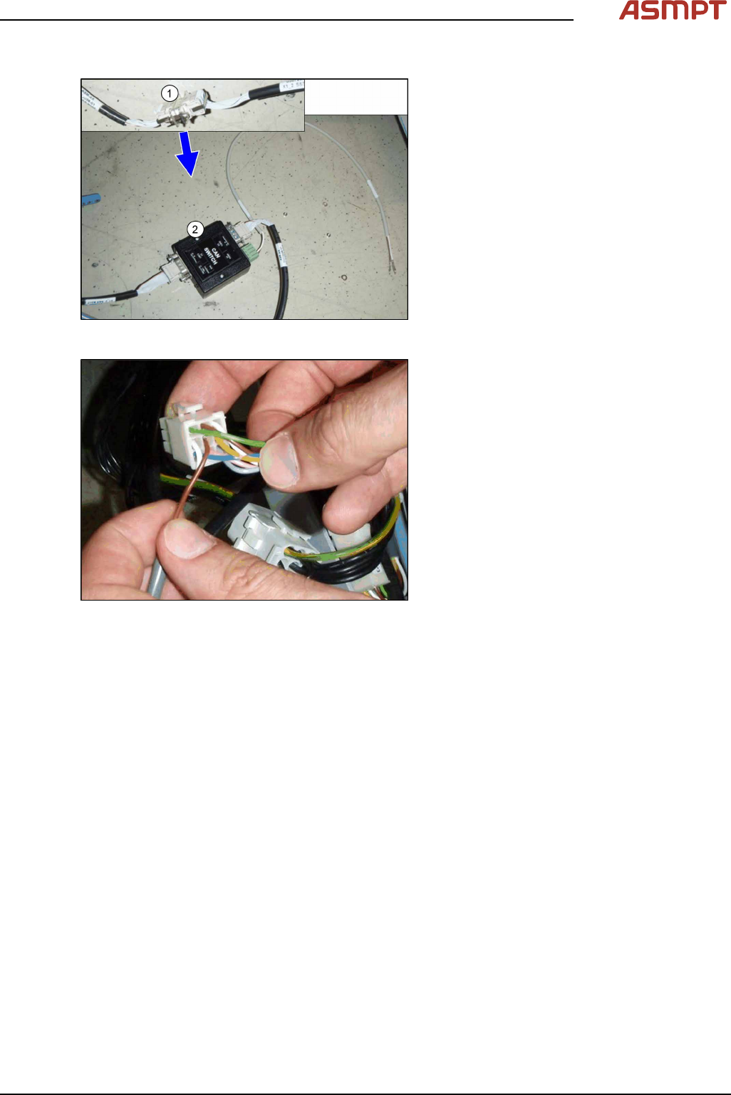
Fig.12: Connecting the CAN switch
► Disconnect the CAN bus (1) inside the in-
frastructure box at point X1_2.
► Set the DIP switches on the CAN-switch
(see 5.1.2 "Setting the DIP Switch on the
CAN Switch" [}76]).
► Plug the CAN switch (2) between the two
cables. Move the stud and screws in a
way, that each connector is fixed with at
least one screw on the CAN switch.
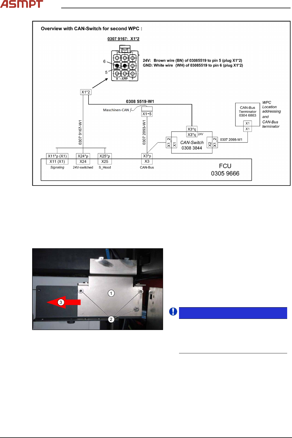
Fig.13: Connecting the power supply
► Connect the power supply to the 9‑pin
connector X112 (location1) or X132 (loca-
tion2). Make sure that both pins engage
correctly. Tug gently on the cable to
check.
► Make sure that the cables are stowed cor-
rectly inside the infrastructure box and
fasten them with cable ties.
► Repeat the installation of the CAN switch
on the second location.
3 Setting up and Commissioning
62 Montageanleitung / Assembly Instructions WPC an/on SIPLACE SX1/SX2 - 03/2025
Fig.14: Detailed circuit diagram CAN switch
► Set the DIP switches on the "CAN-Bus terminator component table" [03046863-xx] (see 5.1.3
"CAN bus terminator for CO table [03046863-xx]" [}77]).
3.3 Installing the Component Trolley Feed Device for the WPC5
► Dismantle the bracket for checking the table height on the right and left hand side. For more infor-
mation, read section 5.1.1 "Downholder" [}69].
Fig.15: Angle plate (here: left)
The angle plates (1) on the left and right must
be fixed in the outermost position.
► If the angle plates are in the innermost
position, move them to the outermost posi-
tion (3). To do this, loosen the three
screws (2) fastening the angle plates and
then fix the plates in the outermost posi-
tion.
NOTICE!
When using the WPC5, the angle plates
must always be fitted in the outermost
position! You may need to move them to
the outermost position if they are not
already there.
.
3 Setting up and Commissioning
Montageanleitung / Assembly Instructions WPC an/on SIPLACE SX1/SX2 - 03/2025 63
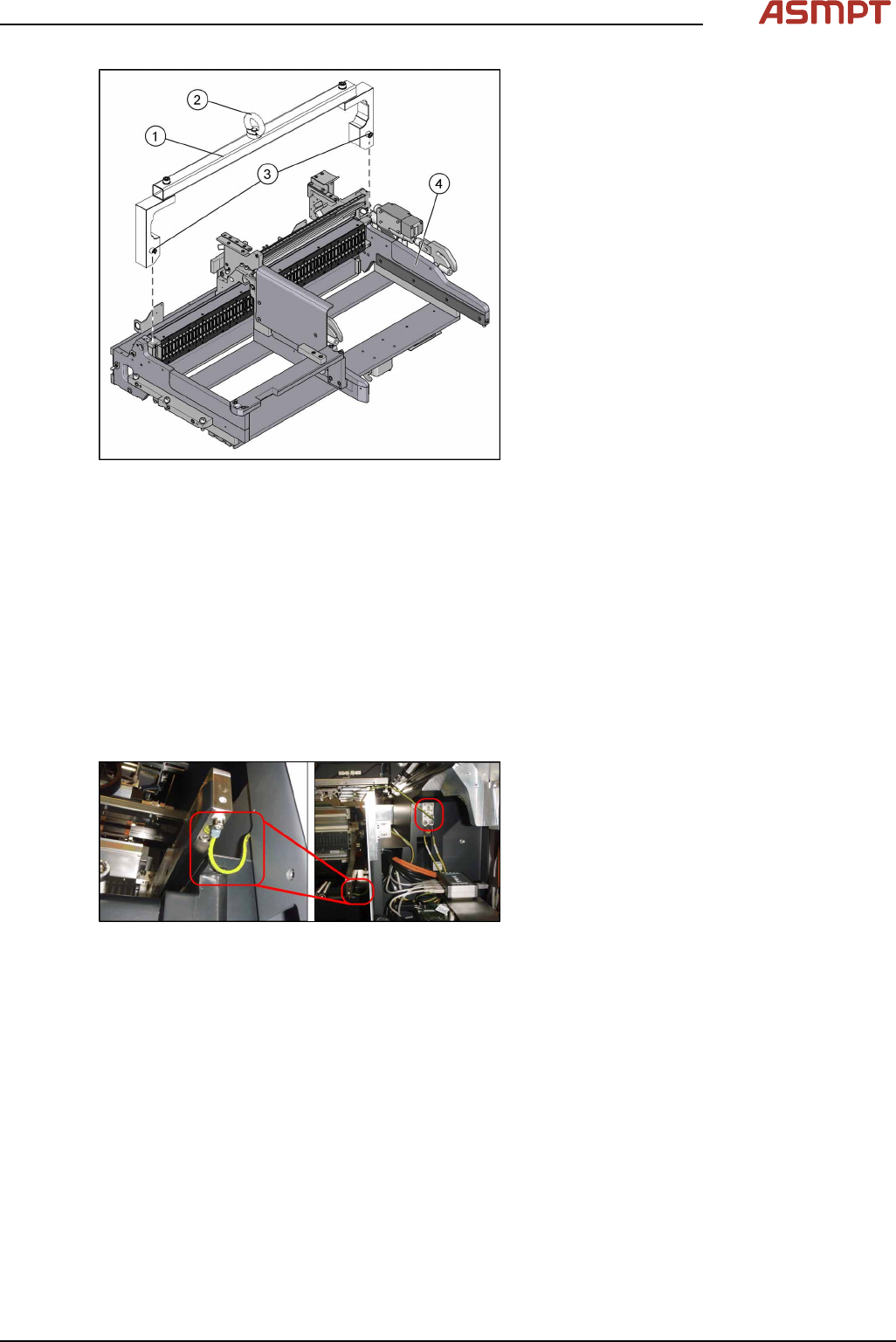
Fig.16: Mounting tool (example of X-Series shown)
1. Mounting tool
2. Eyelet
3. Fastening screws
4. WPC5 feed device
► Attach the fit-up aid to the component trol-
ley feed device.
► Hook the feed device up to the lifting
device by its eyelet.
► Lift the feed device with the lifting device
and move this carefully into the machine
but do not lower it fully yet.
► Carefully thread the cable tree into the machine frame, on the right.
► Lower the feed device onto the contact surface and remove the lifting device.
► Dismantle the lifting device from the feed device.
► Hold the bracket from below, against the feed device and screw this tight with three screws on
each side. Make sure that the nibs on the brackets fit exactly into the recesses in the feed device.
► To the right of the feed device in sector2 or4 you will find the compressed air hose "COT1/2".
Run this through the base, behind the feed device, and up.
► Connect the hose to the Y distributor of the feed device. This is located under the nozzle reject
bin holder.
► Restore all electrical connections to and from the feed device.
Fig.17: Grounding the cable
► Earth the feed device by connecting the
cable to the machine base as shown.
► Fit the bracket for checking the table height onto the right-hand side. Make sure that the nib is po-
sitioned correctly.
The bracket on the left hand side is not needed.
For more information about this, read section 5.1.1 "Downholder" [}69].
► Tighten the screws fastening the angle plates on the left and right.
► Fit the cutter by following the instructions in reverse order.
► Fit the right-hand nozzle changer by following the instructions in reverse order. The left-hand
nozzle changer is not needed.