WPC an:on SIPLACE SX1:SX2 Montageanleitung : Assembly Instructions.pdf - 第73页
5 Appendix Mo nt ag ea nl ei tu ng / A ss em bl y In st ru ct io ns W PC a n/ on S IP LA CE S X1 /S X2 - 0 3/ 20 25 73 NOTICE Screws Insert the new screws into the holes in the downholder and position the downholder toge…
5 Appendix
72 Montageanleitung / Assembly Instructions WPC an/on SIPLACE SX1/SX2 - 03/2025
When the changeover table is in the inner position, the downholder pin(1) is moved approx. 125mm
inwards, towards the docking aid(3) and the downholders are fixed with two new screws each to the
position(4), together with the changeover table insert.
When the changeover table is in the outer position, the downholder pin(2) is underneath the docking
aid(3) and the downholders are fixed with two new screws each to the position(5), together with the
changeover table insert.
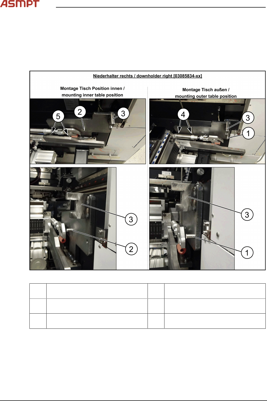
Fitting the right downholder
Fig.26: Downholder
1 Pin DIN6325-10-M6x30-St [00358814-xx]
at position inside
2 Pin DIN6325-10-M6x30-St [00358814-xx]
at position outside
3 Docking aid 4 Screw ISO4762-M8x40-A2-70
[03042589-xx]
5 Screw ISO4762-M8x40-A2-70
[03042589-xx]
► Remove the two screws(4) and(5) on the right side of the changeover table insert. The screws
are underneath the changeover table insert cylinder.
► Place the "downholder COT-i right assembly" [03085834-xx] on the right side of the changeover
table insert so that the holes are aligned with one another.
► Screw the downholder tight with the two new screws(4) and(5).
► The downholder pin(2) must always be approx. 10mm before the claws of the changeover table
insert and the docking aid(3), behind the machine protection (cover flap).
5 Appendix
Montageanleitung / Assembly Instructions WPC an/on SIPLACE SX1/SX2 - 03/2025 73
NOTICE
Screws
Insert the new screws into the holes in the downholder and position the downholder together with the
screws onto the changeover table insert.
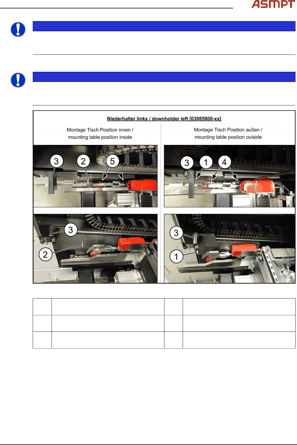
Fitting the left downholder
NOTICE
COT-I30-changeover table insert for the WPC
When using a COT-I30 changeover table insert for the WPC, you only need to fit the downholder on
the right.
Fig.27: Downholder
1 Pin DIN6325-10-M6x30-St [00358814-xx]
at position inside
2 Pin DIN6325-10-M6x30-St [00358814-xx]
at position outside
3 Docking aid 4 Screw ISO4762-M8x40-A2-70
[03042589-xx]
5 Screw ISO4762-M8x40-A2-70
[03042589-xx]
► Remove the two screws(4) and(5) on the left side of the changeover table insert.
► Place the "downholder COT-i left assembly" [03085800-xx] on the left side of the changeover
table insert so that the holes are aligned with one another.
► Screw the downholder tight with the two new screws(4) and(5).
► The downholder pin(2) must always be approx. 10mm before the claws of the changeover table
insert and the docking aid(3), behind the machine protection (cover flap).
5 Appendix
74 Montageanleitung / Assembly Instructions WPC an/on SIPLACE SX1/SX2 - 03/2025
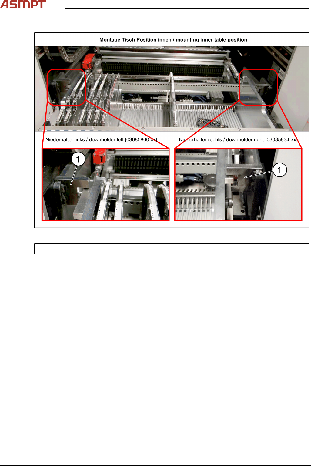
Checking the downholder positions
Fig.28: Changeover table position
1 Docking aid
► Move the changeover table back into the machine.
► The changeover table height must be adjusted so that the side rails fit into the recess on the
docking aid(1).
See also Setting the Changeover Table Height