WPC an:on SIPLACE SX1:SX2 Montageanleitung : Assembly Instructions.pdf - 第75页
5 Appendix Mo nt ag ea nl ei tu ng / A ss em bl y In st ru ct io ns W PC a n/ on S IP LA CE S X1 /S X2 - 0 3/ 20 25 75 Fig.29: Changeover table position 1 Downholder pin on the docking aid 2 Changeover table downholder …
5 Appendix
74 Montageanleitung / Assembly Instructions WPC an/on SIPLACE SX1/SX2 - 03/2025
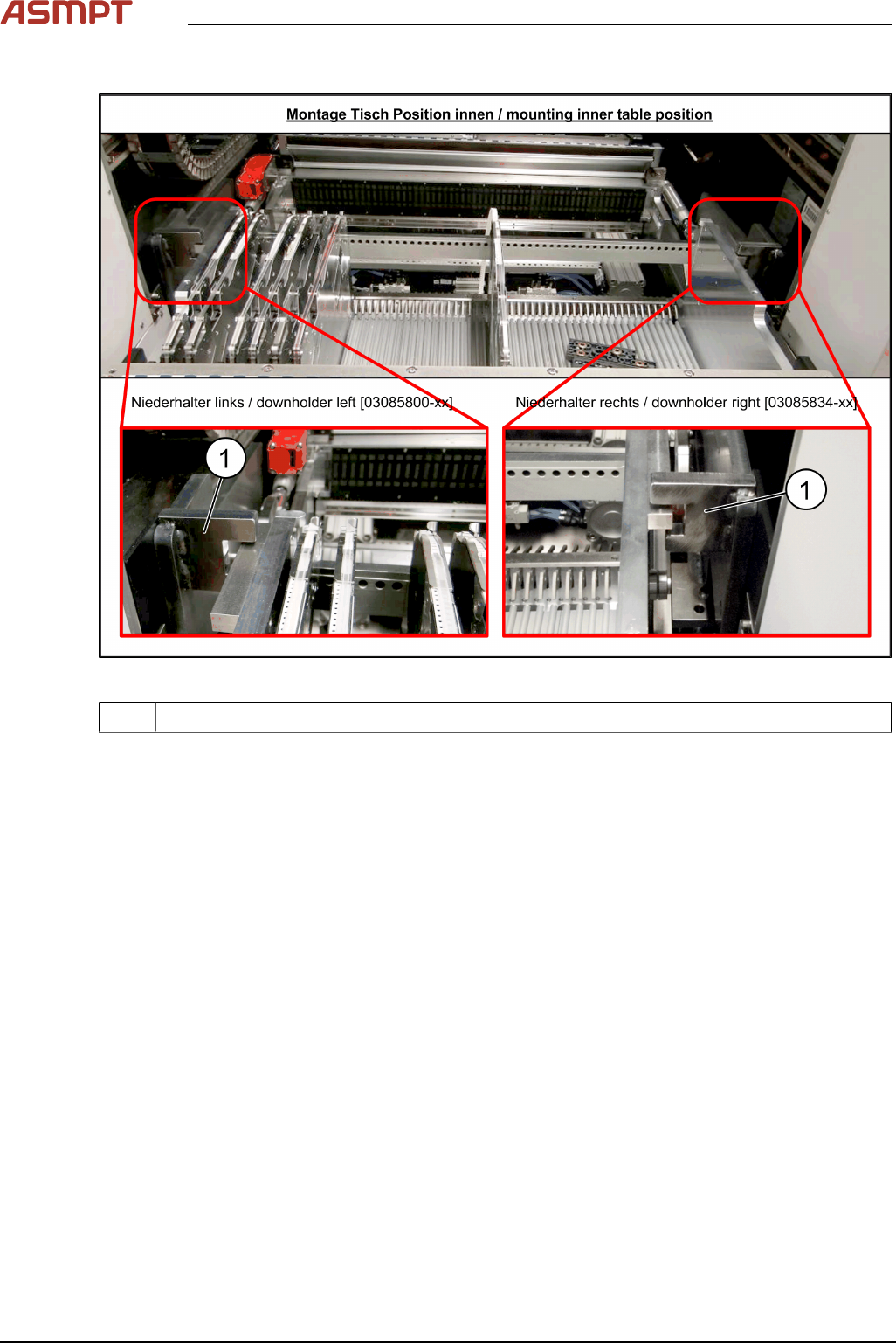
Checking the downholder positions
Fig.28: Changeover table position
1 Docking aid
► Move the changeover table back into the machine.
► The changeover table height must be adjusted so that the side rails fit into the recess on the
docking aid(1).
See also Setting the Changeover Table Height
5 Appendix
Montageanleitung / Assembly Instructions WPC an/on SIPLACE SX1/SX2 - 03/2025 75
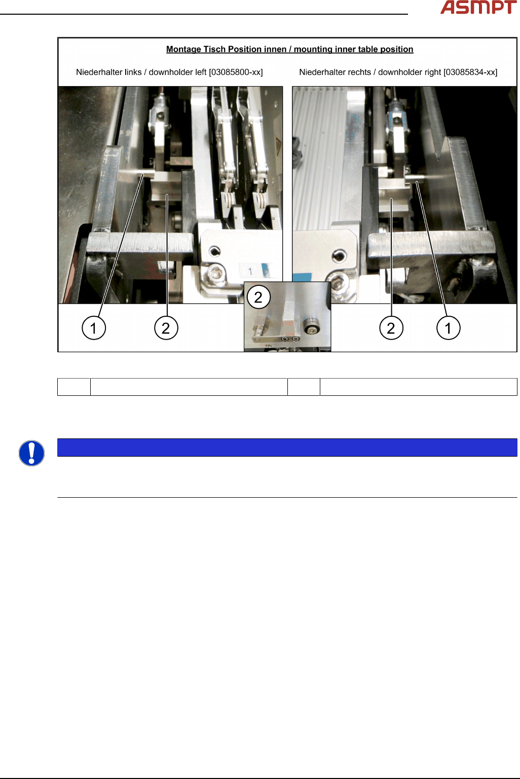
Fig.29: Changeover table position
1 Downholder pin on the docking aid 2 Changeover table downholder
► After pulling the table in through the cylinder, the downholder pin(1) should be up, against the
changeover table downholder(2).
NOTICE
Wear
In the event of frequent changeover table cycle changes, these parts may become worn. Both the
downholder pin and the changeover table downholder are available as spare parts.
5 Appendix
76 Montageanleitung / Assembly Instructions WPC an/on SIPLACE SX1/SX2 - 03/2025
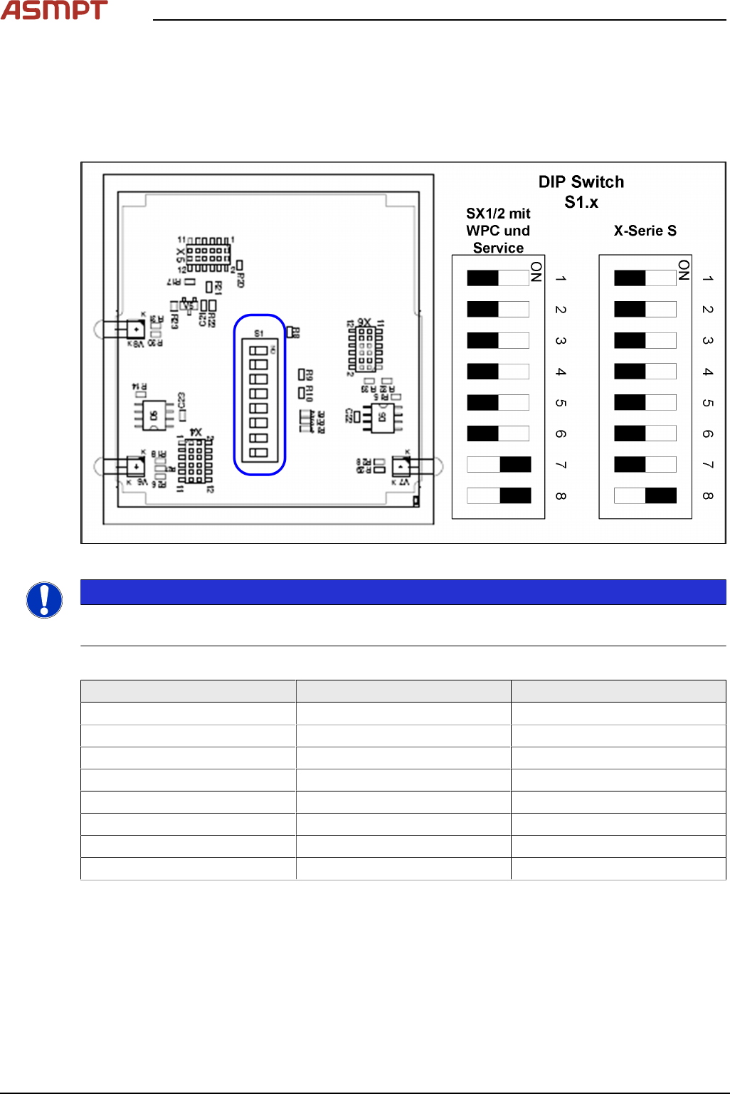
5.1.2 Setting the DIP Switch on the CAN Switch
► Disconnect the CAN switch from the voltage supply.
► Loosen the two screws fastening the upper section (side with label) and remove this upper sec-
tion.
► Set the DIP switches:
Fig.30: Board in CAN switch [03083844-xx]
NOTICE
Default setting
The CAN switch is preset as a default for the SIPLACE X-Series S.
DIP switch S1 in CAN switch [03083844-xx]
DIP switch S1 ON OFF
S1.1 Test mode Normal mode
S1.2 500 kBaud 1 MBaud
S1.3 See table below See table below
S1.4 See table below See table below
S1.5 See table below See table below
S1.6 ASC Test ON ASC Test OFF
S1.7 120 Ohm CAN 1 No terminal resistor
S1.8 120 Ohm CAN 2 No terminal resistor
The DIP switch setting S1.3 to S1.5 is used to configure the display (LED) i.e the number of error
frames needed for the LED to change its status from green to red. The default setting is that the LED
turns red for each error frame received.