WPC an:on SIPLACE SX1:SX2 Montageanleitung : Assembly Instructions.pdf - 第78页
5 Appendix 78 Mo nt ag ea nl ei tu ng / A ss em bl y In st ru ct io ns W PC a n/ on S IP LA CE S X1 /S X2 - 0 3/ 20 25 5.1.4 Replacing the Waste Tape Chute Parts, equipment and tools Select the appropriate waste tape chu…
5 Appendix
Montageanleitung / Assembly Instructions WPC an/on SIPLACE SX1/SX2 - 03/2025 77
LED status error frames
LED status S1.3 S1.4 S1.5
1 error frame OFF OFF OFF
5 error frames/minute ON OFF OFF
10 error frames/minute OFF ON OFF
10 error frames/hour ON ON OFF
50 error frames/hour OFF OFF ON
100 error frames/hour ON OFF ON
500 error frames/hour OFF ON ON
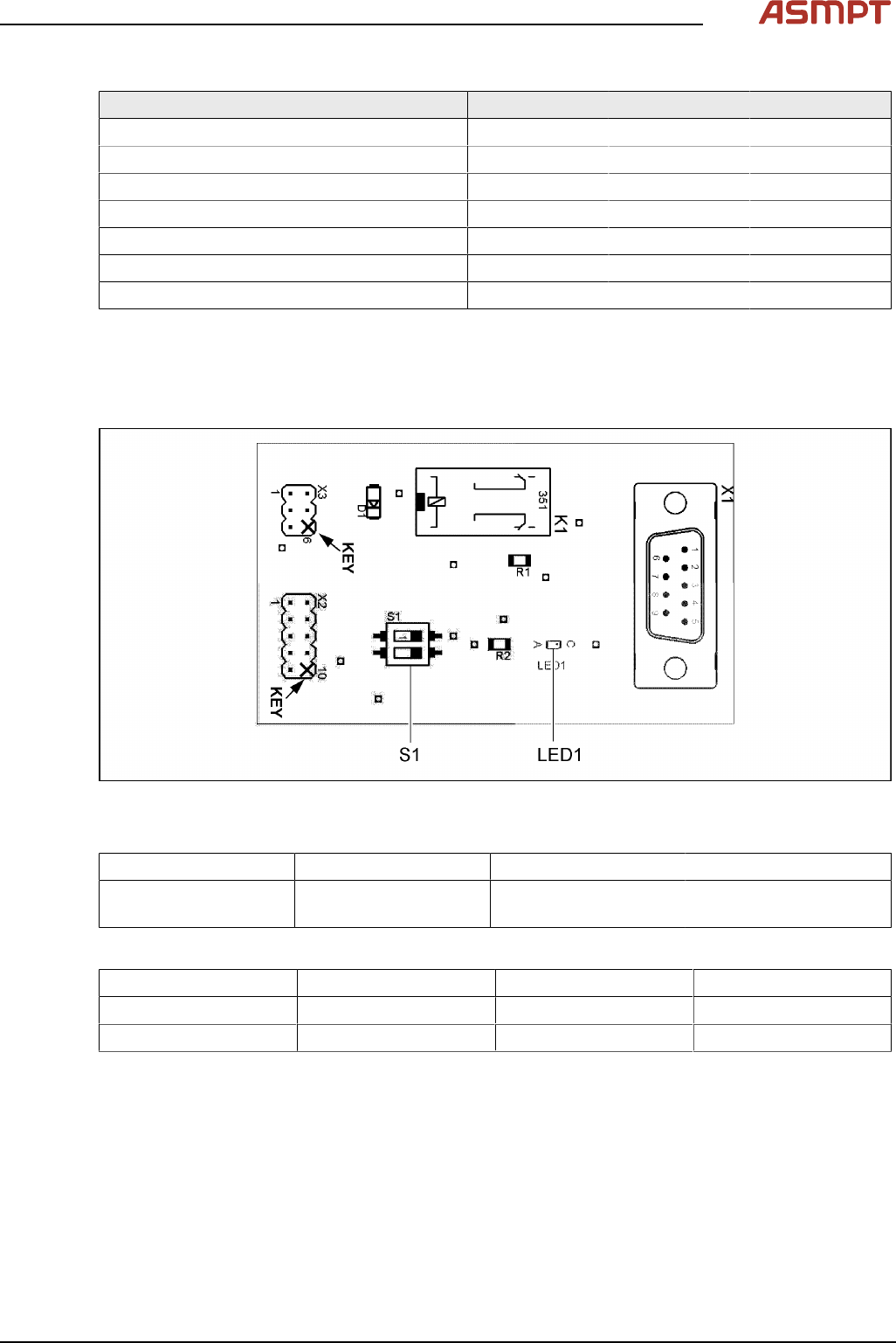
5.1.3 CAN bus terminator for CO table [03046863-xx]
The "CAN bus terminal changeover table" ensures that the CAN bus still works even when a WPC is
fitted. During undocking, a CAN terminating resistor is switched, which maintains the CAN bus function
and communication.
Fig.31: 03046863-01
LED [03046863-01]
LED Color Status Description
LED1 GN ON 24 VDC on connector
X3:4
Switch [03046863-01]
Switch Signal name Location 1 (gantry 1) Location 2 (gantry 2)
S1.1 ADR_0 ON ON
S1.2 ADR_1 ON OFF
5 Appendix
78 Montageanleitung / Assembly Instructions WPC an/on SIPLACE SX1/SX2 - 03/2025
5.1.4 Replacing the Waste Tape Chute
Parts, equipment and tools
Select the appropriate waste tape chute:
Assembly Waste tape chute
Changeover table insert 60 [03059353-xx] Waste tape slide SX1/2 COT60 [03064026-xx]
Changeover table insert 30 [03067206-xx] Waste tape slide SX1/2 COT30 [03073312-xx]
Removal
► Switch off the machine, disconnect it from the power supply and secure it to prevent unauthorized
reactivation.
1.2 "Preparatory work..." [}51]
► Unhook the waste tape chute.
Installation
► Hook the waste tape chute into place.
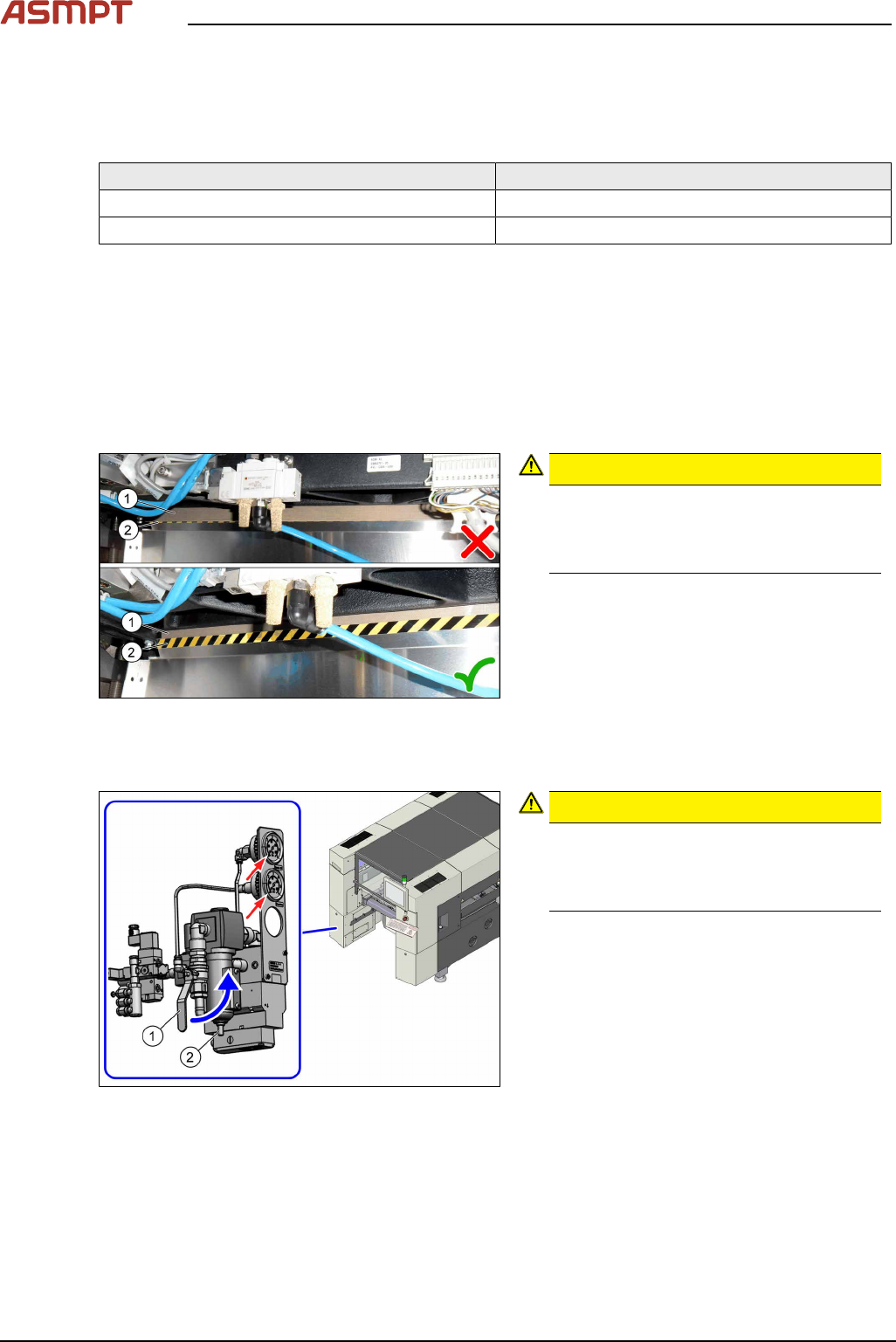
Fig.32: Plastic strips
CAUTION!
Make sure that the plastic strips(1) are
located behind the plate(2).
The black-yellow hatched label must be
completely visible.
.
5.1.5 Disabling the compressed air supply
Fig.33: Shutting off the compressed air supply
CAUTION!
Switch off the compressed air supply
When working on the pneumatic system,
always switch off the compressed air sup-
ply.
.
► Push the lever (1) for the compressed air
supply upwards until it is positioned hori-
zontally.
► Open the screw (2) on the inlet filter to
vent the system. Hold a cloth underneath
to capture any escaping liquid.
► All pressure gauges must be set to zero.
If you are working on cutters, you will need to vent these as follows: