00198536-02_AI_Mixed-Mode_TX2iV1_TX2V2_de_en - 第106页
4 Appendix 4.1 Excerpts from the Service Manual 106 Assembly Instructions / Montageanleitung SIPLACE TX2i V1 SIPLACE TX2 V2 Option Mixed-Mode 01/2019 Removal ► Switch off the machine, disconnect it from the power supply …
4 Appendix
4.1 Excerpts from the Service Manual
Assembly Instructions / Montageanleitung SIPLACE TX2i V1 SIPLACE TX2 V2 Option Mixed-Mode 01/2019 105
4 Appendix
4.1 Excerpts from the Service Manual
The following chapters are excerpts from the service manual for your machine. If required, further
information is provided there.
●
Service manual SIPLACE TX-Series V1 [DE:00198149‑xx] [EN:00198150‑xx]
●
Service manual SIPLACE TX-Series V2 [DE:00198538‑xx] [EN:00198539‑xx]
4.1.1 Replacing the trailing interface
4.1.2 SIPLACE TX V1
4.1.2.1 Replacing the Trailing Cable Interface
Parts, equipment and tools
●
Trailing interface 1 [03115810-xx]
●
Trailing interface 2 [03115814-xx]
NOTICE
SIPLACE TX micron machines
The functionality level of the trailing interface must be at least -02 for SIPLACE TX micron
machines.
Overview
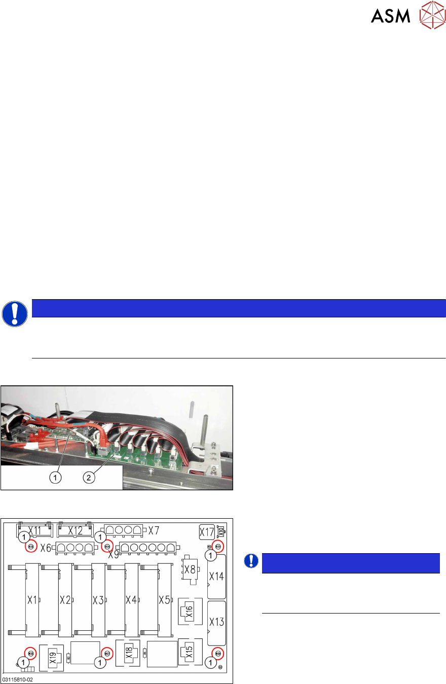
Fig.46: Vision base interface and trailing cable interface
1. Vision base interface (VBI)
2. Trailing cable interface
Fig.47: Trailing interface
Trailing interface [03115810-xx]
1. Six fastening screws
NOTICE!
Inverse layout
The layout of the two trailing interfaces
is the same, but inversely.
.
4 Appendix
4.1 Excerpts from the Service Manual
106 Assembly Instructions / Montageanleitung SIPLACE TX2i V1 SIPLACE TX2 V2 Option Mixed-Mode 01/2019
Removal
► Switch off the machine, disconnect it from the power supply and secure it to prevent
unauthorized reactivation.
1.2 "Preparatory work..." [}77]
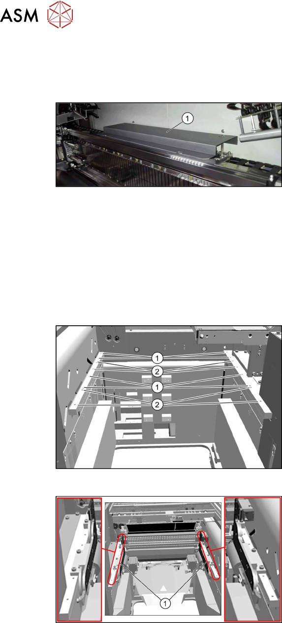
Fig.48: Cover
► Remove the screws fastening the
cover(1) on the trailing cable interface
and remove the cover.
► Unplug the electrical connections to the trailing interface. You may want to mark the position
to make clear assignment easier later on.
► Remove the six screws fastening the trailing interface and remove the interface from the
machine.
Installation
► Follow the removal instructions in reverse order for installation.
4.1.2.2 Installation Positions of COT Insert (Table Positions)
Fig.49: Installation positions
The inner and outer mounting positions de-
pend on the machine type.
The following installation positions apply to
the SIPLACE TX-Series:
1. COT insert at inner position:
SIPLACE TX1, TX2: location 2
SIPLACE TX2i: location 1 and 2
2. COT insert at outer position:
SIPLACE TX1, TX2: location 1
Fig.50: Example: inner position
Example:
1. COTi central unit mounted at inner
position
4 Appendix
4.1 Excerpts from the Service Manual
Assembly Instructions / Montageanleitung SIPLACE TX2i V1 SIPLACE TX2 V2 Option Mixed-Mode 01/2019 107
4.1.2.3 Replacing the COT-i-i central unit and lifting mechanics
NOTICE
Working on the COT-i without complete removal of this
For some tasks on the COT-i, it may be enough to just pull the COT-i slightly out of the
machine. In this case, follow the procedure for replacement but observe the following
instructions:
► Remove the screws fastening the central unit and the lifting mechanics.
► You don't usually need to disconnect the cable. However, if the cable is too short,
unplug it.
► Slightly pull the COT-i out of the machine.
WARNING
Heavy machine parts
► Make sure that the COT-i does not fall out of the machine!
Overview
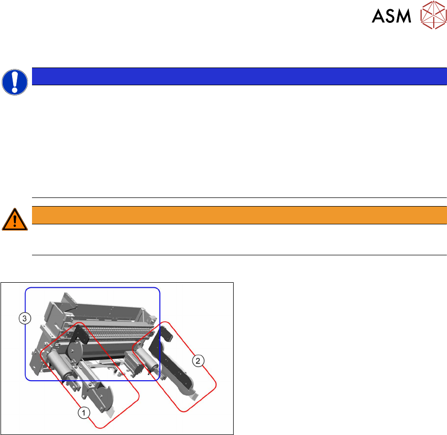
Fig.51: COT‑i parts
The COT-i for SIPLACE TX machines is split
into three separate parts (units) which are
mounted directly to the machine frame.
These parts are as follows:
1. Lifting mechanics left
2. Lifting mechanics right
3. COT-i central unit
The parts are directly fixed with eight screws
to the machine frame (four screws at the
COT-i central unit and two screws on each
of the lifting mechanics).
For the positions of the COT-i in the machine see 4.1.2.2 "Installation Positions of COT Insert
(Table Positions)" [}106].