00198536-02_AI_Mixed-Mode_TX2iV1_TX2V2_de_en - 第110页
4 Appendix 4.1 Excerpts from the Service Manual 110 Assembly Instructions / Montageanleitung SIPLACE TX2i V1 SIPLACE TX2 V2 Option Mixed-Mode 01/2019 Removing the COT-i central unit CAUTION Heavy machine part! The COT-i …
4 Appendix
4.1 Excerpts from the Service Manual
Assembly Instructions / Montageanleitung SIPLACE TX2i V1 SIPLACE TX2 V2 Option Mixed-Mode 01/2019 109
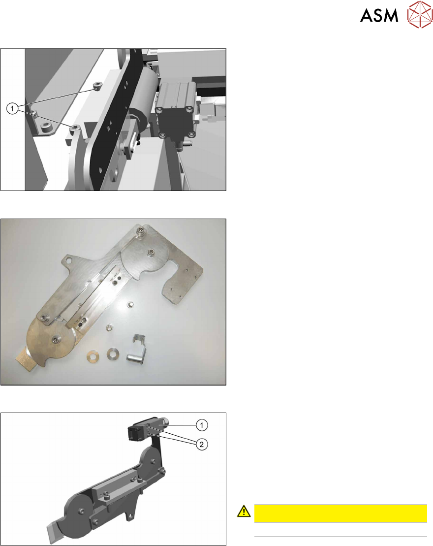
Fig.54: Removing the lifting mechanics
► Dismantle the lifting mechanics by re-
moving the screws(1).
Fig.55: Lifting mechanics parts
► Take out the "left lifting mechanics
assembly" [03126040‑xx].
Fig.56: Safety switch
► Repeat for the right lifting mechanics if
necessary.
The procedure for the right lifting mechanics
is the same, the only difference being that
the safety switch(1) must be removed.
► Remove the two fastening screws(2) of
the safety switch.
CAUTION!
Do not loose the sleeves.
.
4 Appendix
4.1 Excerpts from the Service Manual
110 Assembly Instructions / Montageanleitung SIPLACE TX2i V1 SIPLACE TX2 V2 Option Mixed-Mode 01/2019
Removing the COT-i central unit
CAUTION
Heavy machine part!
The COT-i central unit is heavy. To lift it out, you will need to use the fit-up aid and a suit-
able lifting device (hand-operated crane etc.).
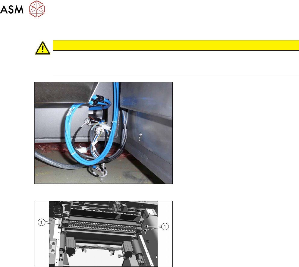
Fig.57: Central unit connections
► Disconnect all connections to the cent-
ral unit.
Fig.58: Central unit fastening screws
► Remove the four fastening screws(1).
► Remove the central unit out of the
machine.
4 Appendix
4.1 Excerpts from the Service Manual
Assembly Instructions / Montageanleitung SIPLACE TX2i V1 SIPLACE TX2 V2 Option Mixed-Mode 01/2019 111
Installation of central unit
Follow the removal instructions in reverse order for installation.
► If necessary move the cutter and the FCU from the old to the new COT-i.
► Lift the COT-i out of the machine. Use a suitable lifting device.
► Reconnect all cables and hoses. Observe the detailed circuit diagram, if needed.
► Move the COT-i into its final position on the machine frame.
Take care not to damage the cables and hoses.
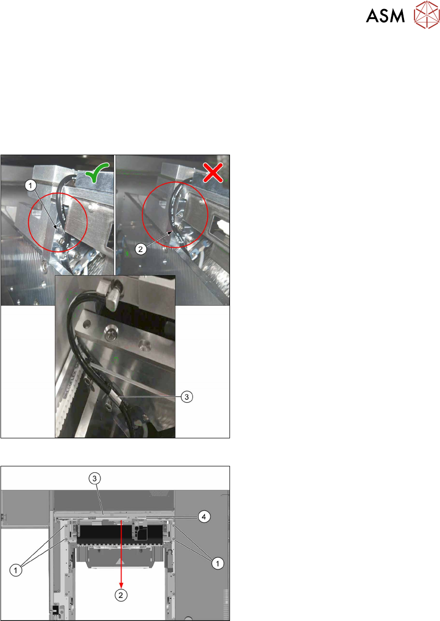
Fig.59: Hoses for the nozzle station air supply
► Check the hoses for the nozzle station
air supply:
1. Hose 1 is recommended. The hose is
running behind the screw head, so the
lining of the hose will not touch the con-
veyor belt.
2. Hose 2 is not recommended, as it may
touch the conveyor belt and will be cut
over time.
3. Use the hose clamp.
Fig.60: Fixing the central unit (shown from above)
► Put in the four screws(1) in position
and loosely tighten them.
► Move the central unit to the outer side
of the machine(2) to ensure a max-
imum distance(4) to the conveyor
side(3).
► The further installation of the central unit is performed by following the above instructions in
the reverse order.