00198536-02_AI_Mixed-Mode_TX2iV1_TX2V2_de_en - 第120页
4 Appendix 4.1 Excerpts from the Service Manual 120 Assembly Instructions / Montageanleitung SIPLACE TX2i V1 SIPLACE TX2 V2 Option Mixed-Mode 01/2019 Installation Fig.72: Trailing unit interface 1 and 2 - connections ► …
4 Appendix
4.1 Excerpts from the Service Manual
Assembly Instructions / Montageanleitung SIPLACE TX2i V1 SIPLACE TX2 V2 Option Mixed-Mode 01/2019 119
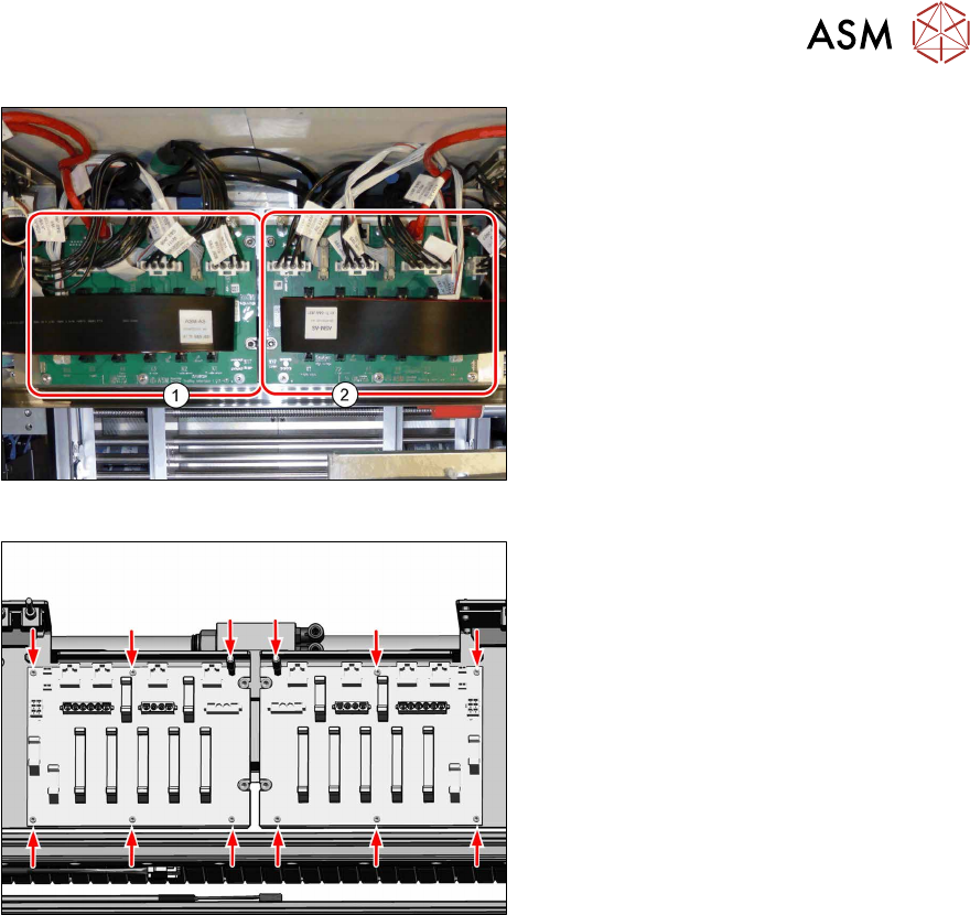
Fig.70: Trailing unit interface 1 and 2
► Unplug the electrical connections from
the relevant trailing unit interface. You
might like to mark their positions to
make clear assignment easier later on.
Fig.71: Screws
► Remove the six screws and bolts
fastening the relevant trailing unit inter-
face and remove the interface from the
machine.
4 Appendix
4.1 Excerpts from the Service Manual
120 Assembly Instructions / Montageanleitung SIPLACE TX2i V1 SIPLACE TX2 V2 Option Mixed-Mode 01/2019
Installation
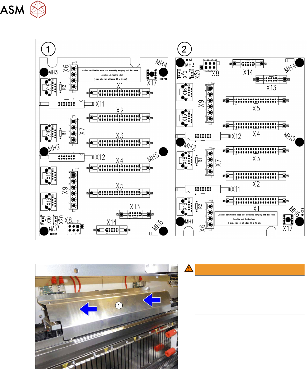
Fig.72: Trailing unit interface 1 and 2 - connections
► Fit the trailing unit interface and restore the electrical connections.
Fig.73: Fitting the cover
WARNING!
Crash hazard!
Make sure that the cover (1) does not
protrude.
A protruding cover could cause a colli-
sion with the gantry.
.
► Before you fix the cover into place,
push it right to the back.
► First, fix the cover with the outer, then
with the two inner screws.
4 Appendix
4.1 Excerpts from the Service Manual
Assembly Instructions / Montageanleitung SIPLACE TX2i V1 SIPLACE TX2 V2 Option Mixed-Mode 01/2019 121
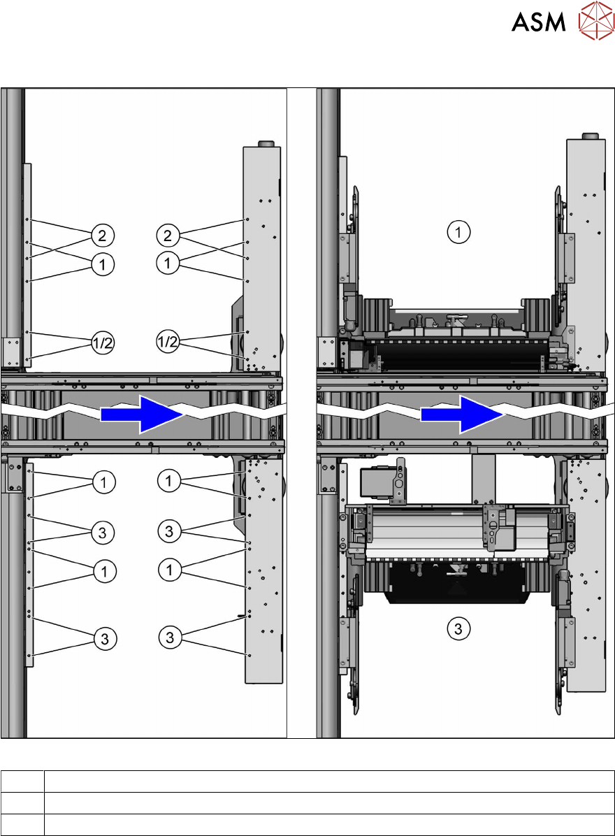
4.1.3.2 Installation Positions of COT Insert (Table Positions)
Fig.74: Installation positions and examples
1 Innermost position (SIPLACE TX2i V2)
2 Innermost position (SIPLACE TX1/TX2 V2 at location 2)
3 Outermost position (SIPLACE TX1/TX2 V2 at location 1)