00198536-02_AI_Mixed-Mode_TX2iV1_TX2V2_de_en - 第123页
4 Appendix 4.1 Excerpts from the Service Manual Assembly Instructions / Montageanleitung SIPLACE TX2i V1 SIPLACE TX2 V2 Option Mixed-Mode 01/2019 123 Overview Fig.76: COT‑i parts The COT-i for SIPLACE TX V2 machines is …
4 Appendix
4.1 Excerpts from the Service Manual
122 Assembly Instructions / Montageanleitung SIPLACE TX2i V1 SIPLACE TX2 V2 Option Mixed-Mode 01/2019
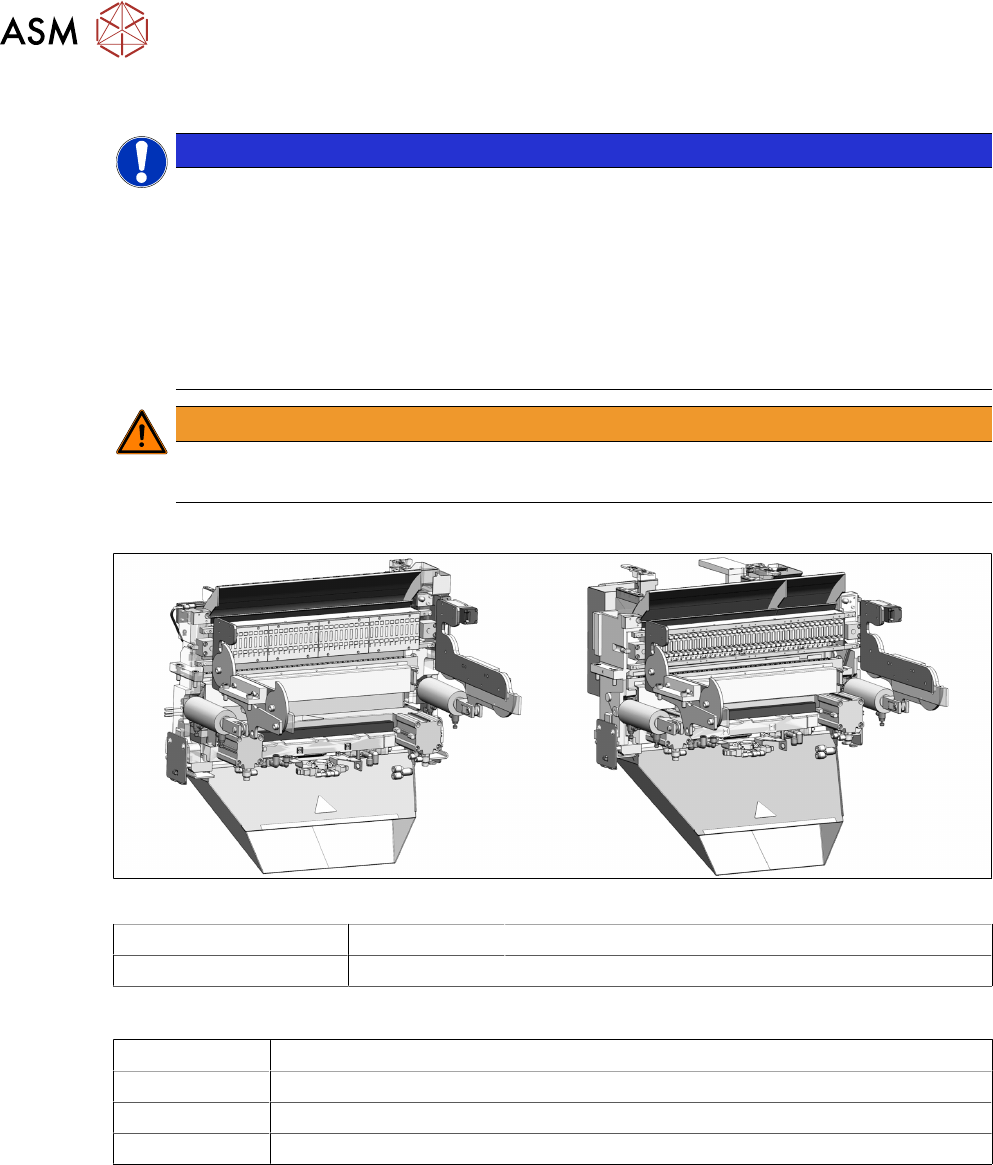
4.1.3.3 Replacing the COT‑i
NOTICE
Working on the COT-i without complete removal of this
For some tasks on the COT-i, it may be enough to just pull the COT-i slightly out of the
machine. In this case, follow the procedure for replacement but observe the following
instructions:
► Remove the screws fastening the central unit and the lifting mechanics.
► You don't usually need to disconnect the cable. However, if the cable is too short, un-
plug it.
► Slightly pull the COT-i out of the machine.
WARNING
Heavy machine parts
► Make sure that the COT-i does not fall out of the machine!
Parts
Fig.75: Assemblies
SIPLACE TX2i V2 03136891-xx COTi TX2i V2 (including cutter and waste tape slide)
SIPLACE TX1/TX2 V2 03146501-xx COTi TX V2 (including cutter and waste tape slide)
Equipment and tools
00353832-xx Allen key set
Wire cutters
Cable ties
Suitable lifting device (e.g. hand-operated crane)
4 Appendix
4.1 Excerpts from the Service Manual
Assembly Instructions / Montageanleitung SIPLACE TX2i V1 SIPLACE TX2 V2 Option Mixed-Mode 01/2019 123
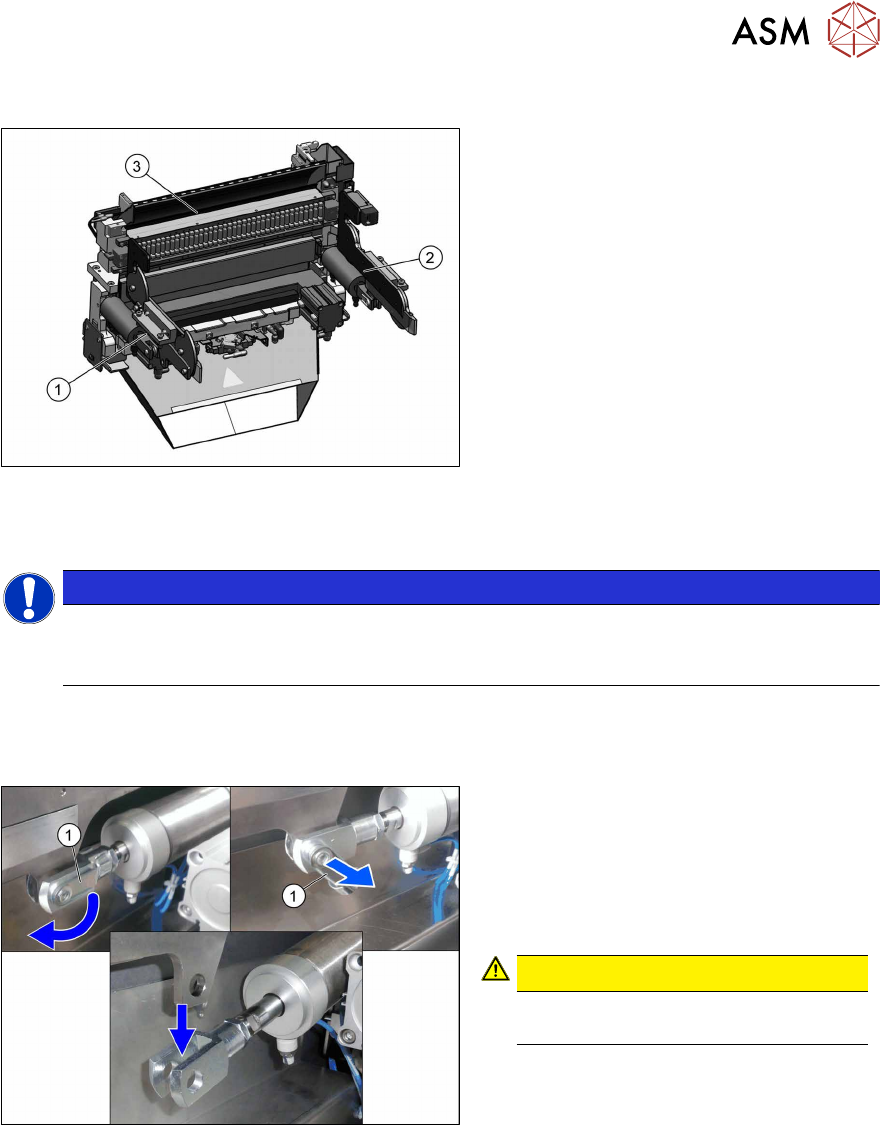
Overview
Fig.76: COT‑i parts
The COT-i for SIPLACE TX V2 machines is
split into three separate parts (units) which
are mounted directly to the machine base.
These parts are as follows:
1. Lifting mechanics left
2. Lifting mechanics right
3. COT-i central unit
The parts are directly fixed with eight screws
to the machine base (four screws at the
COT-i central unit and two screws on each
of the lifting mechanics).
Removal of left and right lifting mechanics
NOTICE
Shown by example
The following procedure is shown by example of the left lifting mechanics. The procedure
for the right lifting mechanics the same. Relevant differences will be mentioned.
► Switch off the machine, disconnect it from the power supply and secure it to prevent
unauthorized reactivation.
1.2 "Preparatory work..." [}77]
Fig.77: Locking flap
The safety bolt(1) fixes the connection
between the pneumatic cylinder and the lift-
ing mechanics.
► Flip the safety catch down.
► Remove the safety bolt, to access the
connection.
CAUTION!
Pay attention to the position and
number of washers used.
.
4 Appendix
4.1 Excerpts from the Service Manual
124 Assembly Instructions / Montageanleitung SIPLACE TX2i V1 SIPLACE TX2 V2 Option Mixed-Mode 01/2019
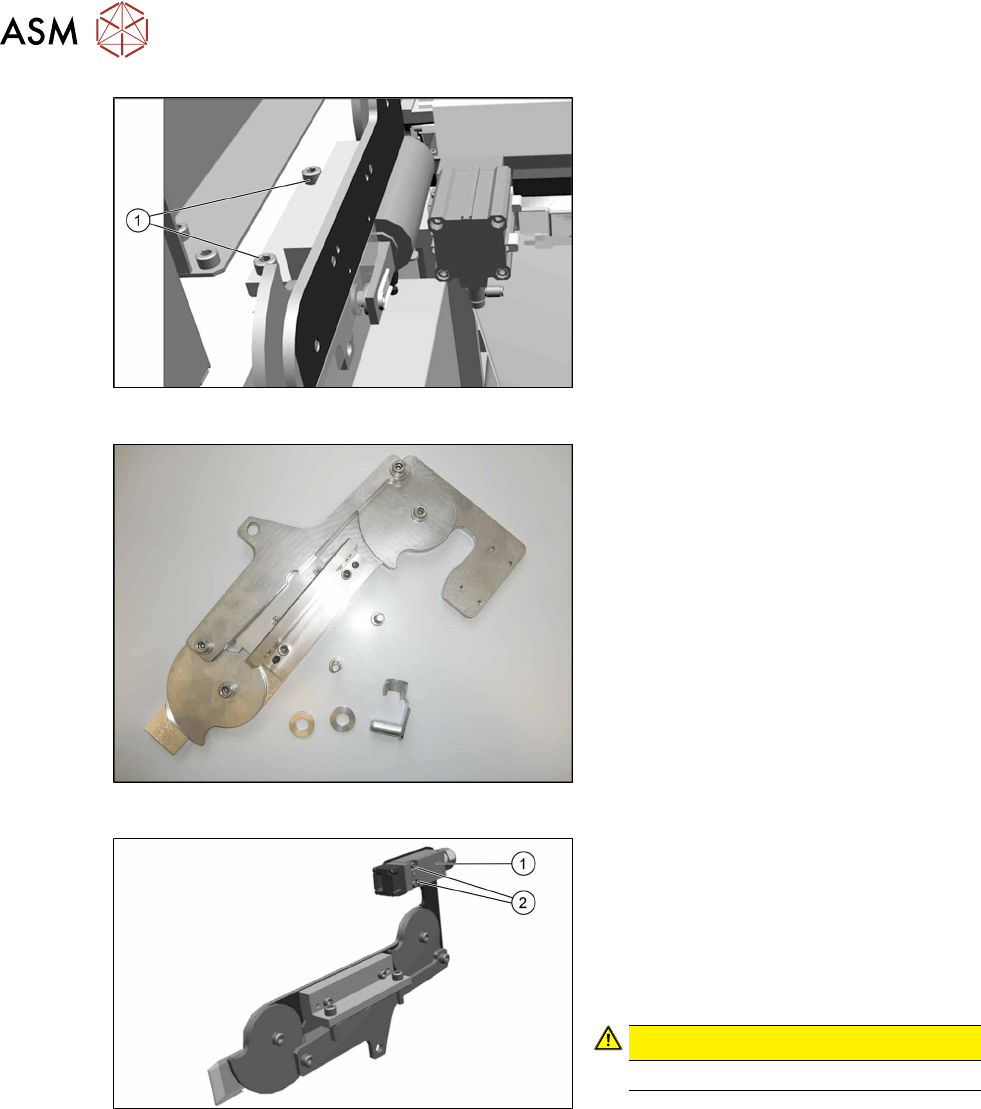
Fig.78: Removing the lifting mechanics
► Dismantle the lifting mechanics by re-
moving the screws(1).
Fig.79: Lifting mechanics parts
► Take out the "left lifting mechanics
assembly" [03126040‑xx].
Fig.80: Safety switch
► Repeat for the right lifting mechanics if
necessary.
The procedure for the right lifting mechanics
is the same, the only difference being that
the safety switch(1) must be removed.
► Remove the two fastening screws(2) of
the safety switch.
CAUTION!
Do not loose the sleeves.
.