00198536-02_AI_Mixed-Mode_TX2iV1_TX2V2_de_en - 第86页
2 Brief description 2.3 Tools and equipment required 86 Assembly Instructions / Montageanleitung SIPLACE TX2i V1 SIPLACE TX2 V2 Option Mixed-Mode 01/2019 2.3 Tools and equipment required The following tools and equipment…
2 Brief description
2.2 Scope of delivery
Assembly Instructions / Montageanleitung SIPLACE TX2i V1 SIPLACE TX2 V2 Option Mixed-Mode 01/2019 85
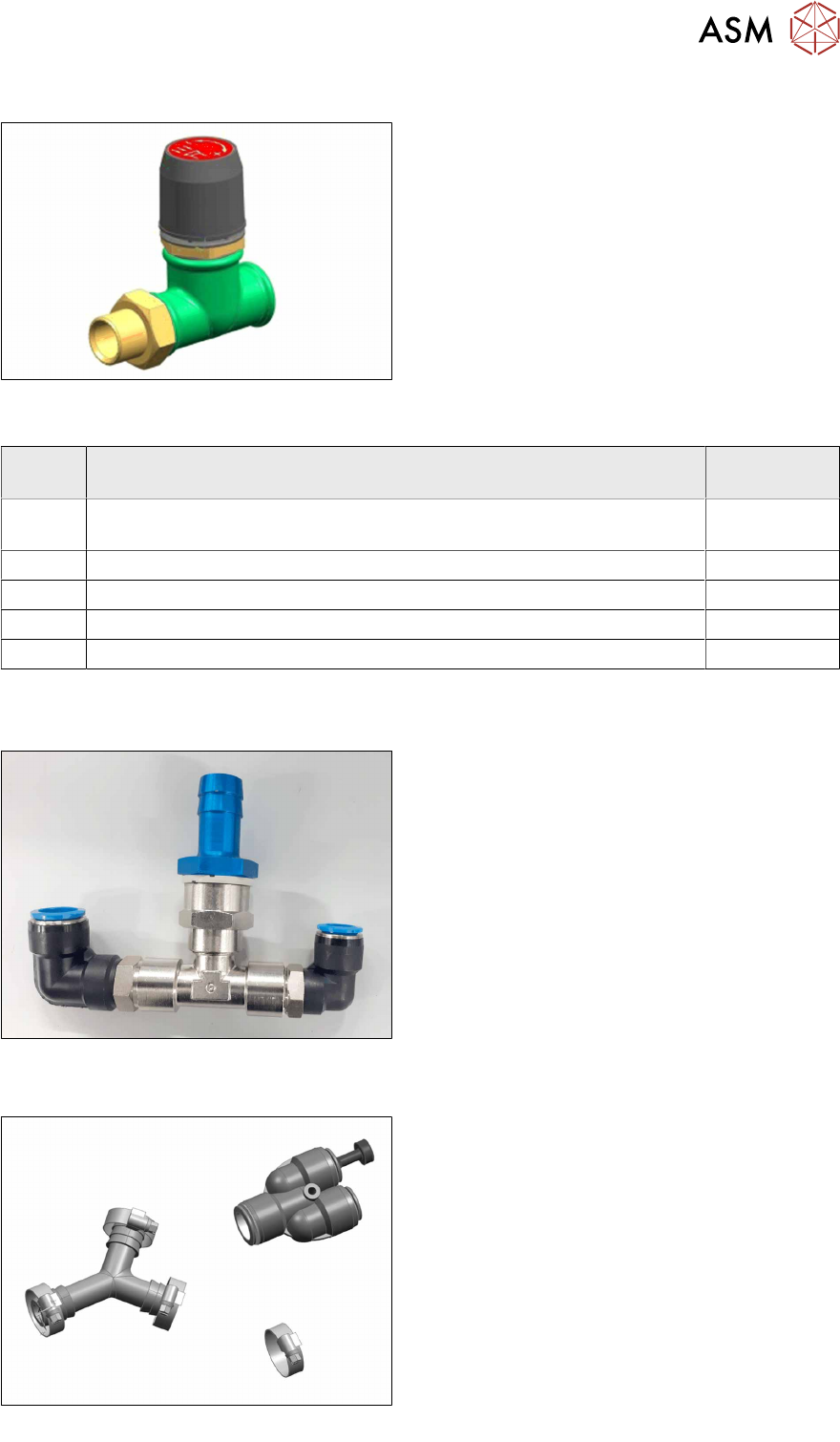
Ordering the vacuum control valve:
Fig.10: Vacuum control valve assembly TX
[03162136‑xx]
The installation of the vacuum control valve is re-
quired, if only one SIPLACE C&P20x head is op-
erated with a vacuum pump. If the machine was
previously operated with a vacuum pump and two
SIPLACE C&P20x heads , this vacuum control
valve was not fitted and must be installed for the
mixed mode function.
Quant-
ity
Designation Item no.
1 Vacuum control valve assembly TX
Consists of:
03162136-xx
1 Vacuum control valve Becker ST 613-0-2 03109300-xx
1 T-piece 3/4" – 1” 03162231-xx
1 Double nipple 3/4" 03038435-xx
1 Thread sealant Loctite 55 03092492-xx
Additionally required parts:
●
Upgrade kit 2 pneumatics [03162637‑xx]
Fig.11: Upgrade kit 2 pneumatics [03162637‑xx]
If the mixed heads option is installed and a
vacuum pump is present, the following upgrade
kit is needed in addition:
If the mixed heads option is installed and no
vacuum pump is present, this upgrade kit is
already installed in the machine.
●
Upgrade kit vacuum pump TX V2 [03162656Sxx]
Fig.12: Upgrade kit vacuum pump TX V2 [03162656Sxx]
This upgrade kit is required if a vacuum pump is
not available yet but will be installed later on.

2 Brief description
2.3 Tools and equipment required
86 Assembly Instructions / Montageanleitung SIPLACE TX2i V1 SIPLACE TX2 V2 Option Mixed-Mode 01/2019
2.3 Tools and equipment required
The following tools and equipment are required for the work described in this manual:
T Standard tooling
T31 00376492-xx Hexagon L-wrench set 1,5-10
T 03079617-xx Depth measuring gauge 300mm
T 00381443‑xx Pipe/hose cutters Festo ZRS 7658
C 03092492-xx Loctite 55
Service manual for your machine
00198147-xx Assembly instructions Vacuum Pump SIPLACE TX V1/V2-Series
2.4 Required Working Time
The complete installation will take approx. 5 hours.
2.5 Prerequisites and restrictions
The mixed mode option can be installed in the following machines:
●
SIPLACE TX2i V1
●
SIPLACE TX2 V2
Assembly on other machines of the TX series is not possible.

3 Installation
3.1 Sealing the Pneumatic Screwed Connections
Assembly Instructions / Montageanleitung SIPLACE TX2i V1 SIPLACE TX2 V2 Option Mixed-Mode 01/2019 87
3 Installation
Please observe the following steps:
●
Modifying the hose connections for the mixed mode
●
Installing the vacuum pump
●
Installing the vacuum control valve
●
Replacing the side sections of the NC (CPP)
●
Replacing the holder for the nozzle reject station
NOTICE
Assembly instructions for the vacuum pump
► Please also observe the assembly instructions for the "Option Vacuum Pump
SIPLACE TX V1/V2-Series" [DE+EN: 00198147‑xx]
3.1 Sealing the Pneumatic Screwed Connections
NOTICE
Sealing the pneumatic screwed connections
If pneumatic screwed connections are loosened, these will need to be sealed again after-
wards. Always use the same sealing technique as was used before they were removed.
The following sealing techniques are available:
► Sealing ring (rubber or plastic)
These are either supplied or you can use the ones used before. Check the condition of
used sealing rings for damage.
► Sealant
There are several variants of this:
Loctite 567 [03097172-xx] and Loctite 55 [03092492-xx]
After loosening the pneumatic screwed connection, clean the screwed thread and seal
it with Loctite. The sealing thread for Loctite 55 must be wound on in the direction of
the screwed thread.
There may also already be a sealant on the screwed thread.
3.2 Adapting the hose connections at the pneumatics block
The pneumatics block is located underneath the trailing interfaces. For this reason, you have to
partially dismantle the interfaces as described in the following sections.
For details about the trailing interface on the SIPLACE TX V1, please refer to section 4.1.2.1 "Re-
placing the Trailing Cable Interface" [}105] (excerpt of the service manual).
For details about the trailing interface on the SIPLACE TX V2, please refer to section 4.1.3.1 "Re-
placing the Trailing Cable Interface" [}118] (excerpt of the service manual).
See also
2 3.2.2.1 "Gantry without vacuum hoses (gantry with CPP)" [}92]
2 3.2.2.2 "Gantry with vacuum hoses(gantry with C&P20x)" [}94]