00198536-02_AI_Mixed-Mode_TX2iV1_TX2V2_de_en - 第91页
3 Installation 3.2 Adapting the hose connections at the pneumatics block Assembly Instructions / Montageanleitung SIPLACE TX2i V1 SIPLACE TX2 V2 Option Mixed-Mode 01/2019 91 Overview - conversion of the hose connections …
3 Installation
3.2 Adapting the hose connections at the pneumatics block
90 Assembly Instructions / Montageanleitung SIPLACE TX2i V1 SIPLACE TX2 V2 Option Mixed-Mode 01/2019
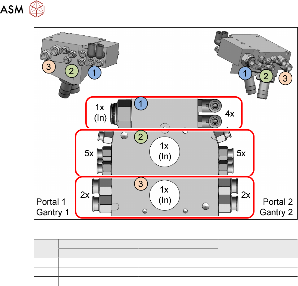
Fig.16: Overview of the three chambers in the pneumatics block with the according connections (Using a
SIPLACETXV2 as example)
Item in
figure
Initial situation With mixed mode
Without vacuum pump With vacuum pump
1 Compressed Air Compressed Air Compressed Air
2 Compressed Air Vacuum Compressed Air
3 Not connected Vacuum Vacuum
3 Installation
3.2 Adapting the hose connections at the pneumatics block
Assembly Instructions / Montageanleitung SIPLACE TX2i V1 SIPLACE TX2 V2 Option Mixed-Mode 01/2019 91
Overview - conversion of the hose connections
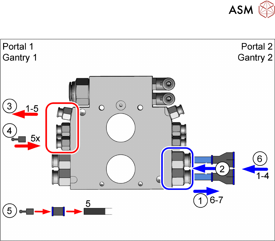
Fig.17: Overview of pneumatics block conversion (using aSIPLACETXV2, as example with gantry 1: vacuum,
gantry 2: compressed air)
1. Removing the Camozzi hoses 6 and 7 (gantry 2')
2. Connecting the two hoses using Y pieces
3. Disconnecting the hoses 1 to 5 (gantry 1)
4. Sealing the connections 1 to 5 (gantry 1)
5. Sealing hose 5
6. Disconnecting the hoses 1 to 4 (gantry 1) to the Y pieces
Steps 1 and 2 are described in section 3.2.2.1 "Gantry without vacuum hoses (gantry with
CPP)" [}92].
Steps 3 to 6 are described in section 3.2.2.2 "Gantry with vacuum hoses(gantry with
C&P20x)" [}94].
3 Installation
3.2 Adapting the hose connections at the pneumatics block
92 Assembly Instructions / Montageanleitung SIPLACE TX2i V1 SIPLACE TX2 V2 Option Mixed-Mode 01/2019
3.2.2.1 Gantry without vacuum hoses (gantry with CPP)
SIPLACE TX V1:
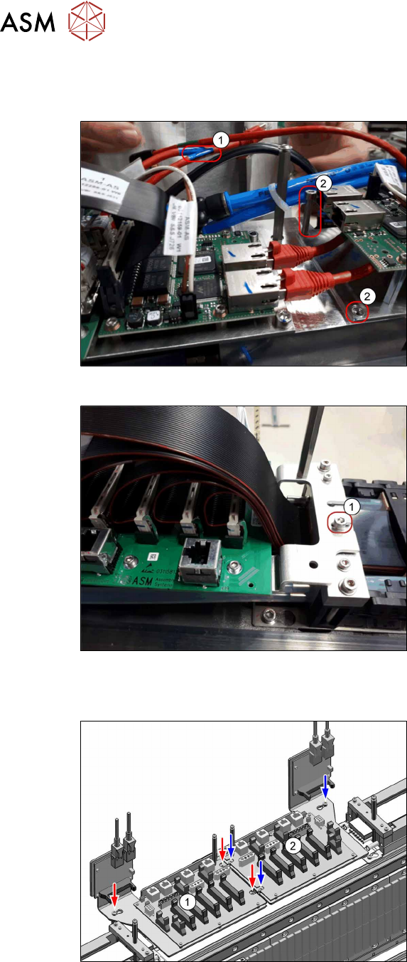
Fig.18: Disconnecting the cables (SIPLACETX2iV1)
► Disconnect the GigE cable(1) from the
VBI.
► Remove both screws (2).
Fig.19: Loosing the screw (SIPLACETX2iV1)
► Loosen the screw(1) (do not remove).
► Put the trailing interface aside, so that
you have good access to the pneumat-
ics block.
SIPLACE TX V2:
Fig.20: Disconnecting the cables (SIPLACETX2V2)
Trailing interface and VBI are mounted on
the same mounting plate. Only the mounting
plate is removed, the boards can stay on the
mounting plate.
► Remove the mounting plate from the
trailing interface(2) (3screws).
► Put the mounting plate with trailing in-
terface and VBI aside.
If necessary, unplug the GigE cables of
the VBI. Make sure that the cables can
be unequivocally assigned again later
on.