00198536-02_AI_Mixed-Mode_TX2iV1_TX2V2_de_en - 第93页
3 Installation 3.2 Adapting the hose connections at the pneumatics block Assembly Instructions / Montageanleitung SIPLACE TX2i V1 SIPLACE TX2 V2 Option Mixed-Mode 01/2019 93 SIPLACE TX V1 and V2: Fig.21: Converting the …
3 Installation
3.2 Adapting the hose connections at the pneumatics block
92 Assembly Instructions / Montageanleitung SIPLACE TX2i V1 SIPLACE TX2 V2 Option Mixed-Mode 01/2019
3.2.2.1 Gantry without vacuum hoses (gantry with CPP)
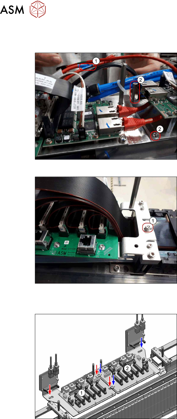
SIPLACE TX V1:
Fig.18: Disconnecting the cables (SIPLACETX2iV1)
► Disconnect the GigE cable(1) from the
VBI.
► Remove both screws (2).
Fig.19: Loosing the screw (SIPLACETX2iV1)
► Loosen the screw(1) (do not remove).
► Put the trailing interface aside, so that
you have good access to the pneumat-
ics block.
SIPLACE TX V2:
Fig.20: Disconnecting the cables (SIPLACETX2V2)
Trailing interface and VBI are mounted on
the same mounting plate. Only the mounting
plate is removed, the boards can stay on the
mounting plate.
► Remove the mounting plate from the
trailing interface(2) (3screws).
► Put the mounting plate with trailing in-
terface and VBI aside.
If necessary, unplug the GigE cables of
the VBI. Make sure that the cables can
be unequivocally assigned again later
on.
3 Installation
3.2 Adapting the hose connections at the pneumatics block
Assembly Instructions / Montageanleitung SIPLACE TX2i V1 SIPLACE TX2 V2 Option Mixed-Mode 01/2019 93
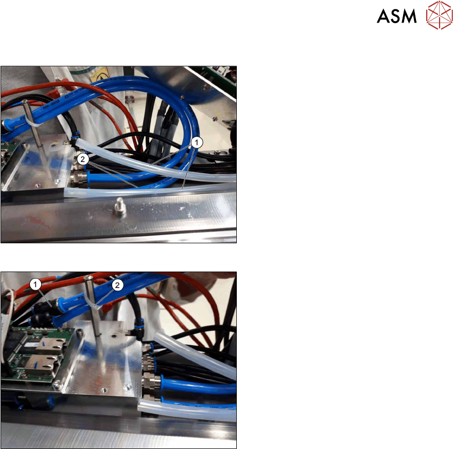
SIPLACE TX V1 and V2:
Fig.21: Converting the hoses (SIPLACETX2iV1)
► Remove the two transparent Camozzi
hoses(1) from the pneumatics block.
Place these hoses next to the pneu-
matics block and fix the hoses using
cable ties. The hoses must not rub any-
where or protrude into the travel range
of the gantries.
► Take the pneumatics hose out of the
retrofit kit and cut the hose into two
pieces of the same length (each ap-
prox. 52 cm).
► Attach the two hose pieces(2) to the
pneumatics block (instead of the previ-
ously removed Camozzi hoses).
Fig.22: Fitting the hoses (SIPLACETX2iV1)
► Connect the two Y pieces to the other
end of the pneumatic hoses(1).
► SIPLACE TX V1: Secure the two pneu-
matic hoses to the stay bolt with a
cable tie(2).
► SIPLACE TX V2: Run the two hoses
beside the pneumatics distributor to the
corresponding trailing cable (here, to
trailing cable of gantry1).
► Secure the two hoses with cable ties to
make sure that the hoses cannot pro-
trude into the travel range of the
gantries.
► Fit the mounting plate with trailing inter-
face and VBI.
3 Installation
3.2 Adapting the hose connections at the pneumatics block
94 Assembly Instructions / Montageanleitung SIPLACE TX2i V1 SIPLACE TX2 V2 Option Mixed-Mode 01/2019
3.2.2.2 Gantry with vacuum hoses(gantry with C&P20x)
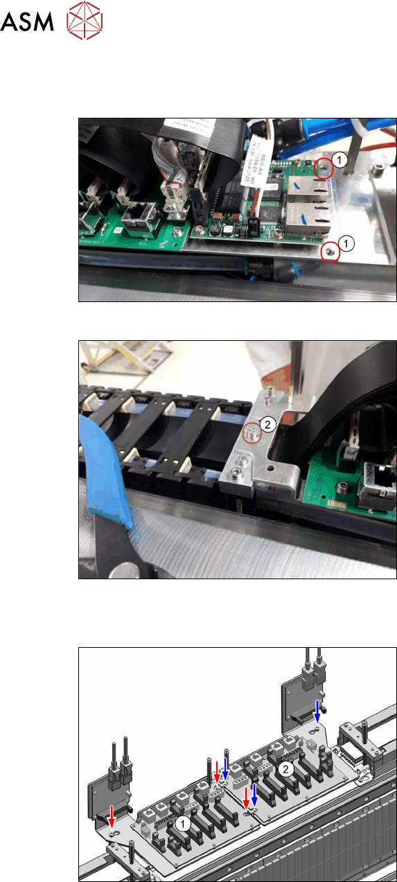
SIPLACE TX V1:
Fig.23: VBI (SIPLACETX2iV1)
Trailing interface and VBI are mounted on
the same mounting plate. Only the mounting
plate is removed, the boards can stay on the
mounting plate.
► Remove both screws (1).
Fig.24: Loosing the screw (SIPLACETX2iV1)
► Loosen the screw(2).
► Put the mounting plate with the trailing
interface and the VBI aside, so that you
have good access to the pneumatics
block lying underneath.
If necessary, unplug the GigE cables
from the VBI. Make sure that the cables
can be unequivocally assigned again
later on.
SIPLACE TX V2:
Fig.25: Trailing interfaces (SIPLACETX2V2)
Trailing interface and VBI are mounted on
the same mounting plate. Only the mounting
plate is removed, the boards can stay on the
mounting plate.
► Remove the mounting plate of the trail-
ing interface(1) (3screws).
► Put the trailing interface and the VBI
aside, so that you have good access to
the pneumatics block lying underneath.
If necessary, unplug the GigE cables
from the VBI. Make sure that the cables
can be unequivocally assigned again
later on.