00198536-02_AI_Mixed-Mode_TX2iV1_TX2V2_de_en - 第97页
3 Installation 3.3 Connecting the vacuum pump Assembly Instructions / Montageanleitung SIPLACE TX2i V1 SIPLACE TX2 V2 Option Mixed-Mode 01/2019 97 3.3.2 Connecting the vacuum pump (SIPLACE TX2i V1) Fig.31: Connection on…
3 Installation
3.3 Connecting the vacuum pump
96 Assembly Instructions / Montageanleitung SIPLACE TX2i V1 SIPLACE TX2 V2 Option Mixed-Mode 01/2019
SIPLACE TX V2:
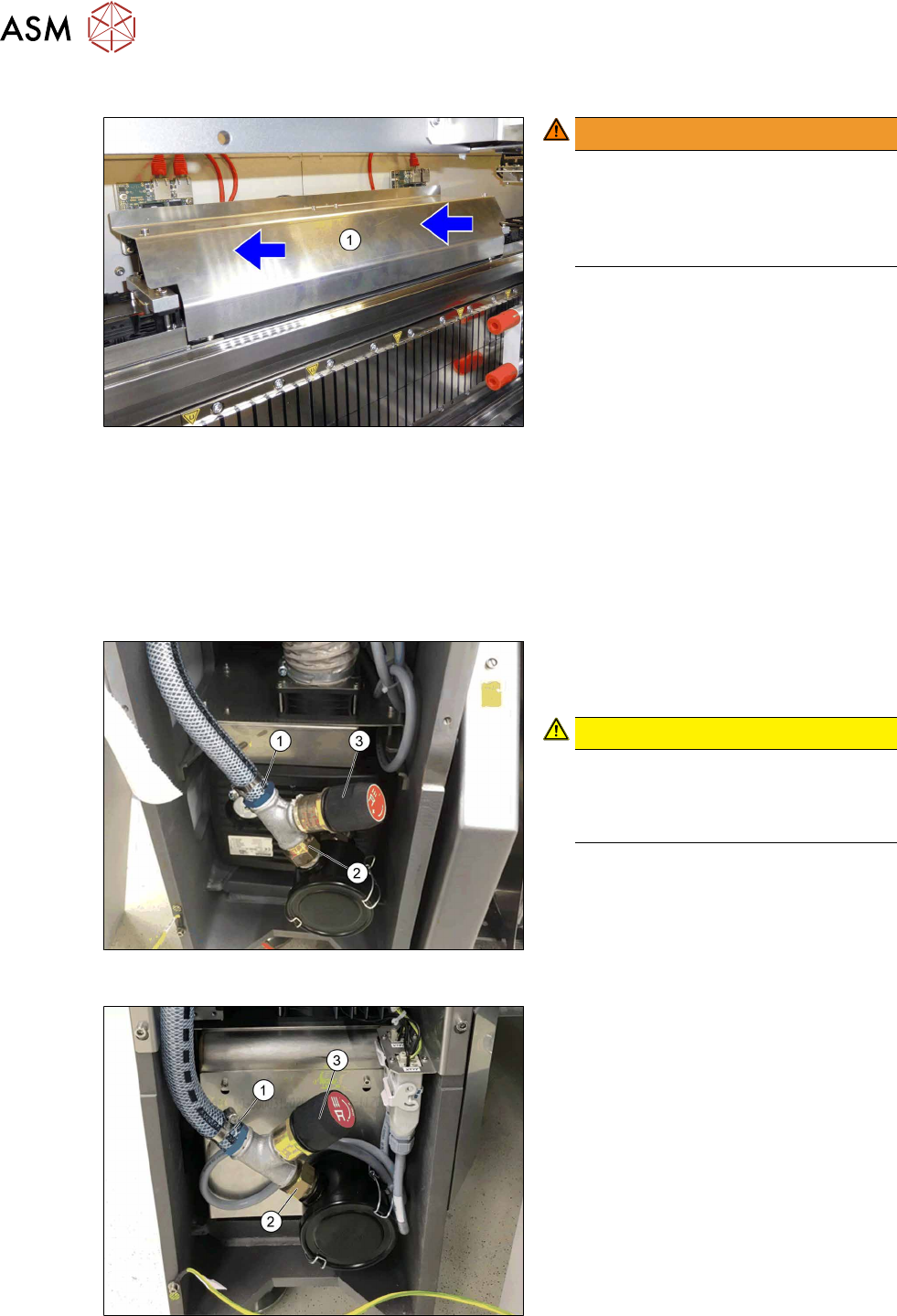
Fig.28: Fitting the cover
WARNING!
Crash hazard!
Make sure that the cover (1) does not
protrude.
A protruding cover could cause a colli-
sion with the gantry.
.
► Before you fix the cover into place,
push it right to the back.
► First, fix the cover with the outer, then
with the two inner screws.
3.3 Connecting the vacuum pump
► If no vacuum pump is installed yet, install it now. Read the assembly instructions for this.
●
Assembly instructions "Option Vacuum Pump SIPLACE TX V1/V2-Series" [DE+EN:00198147‑xx]
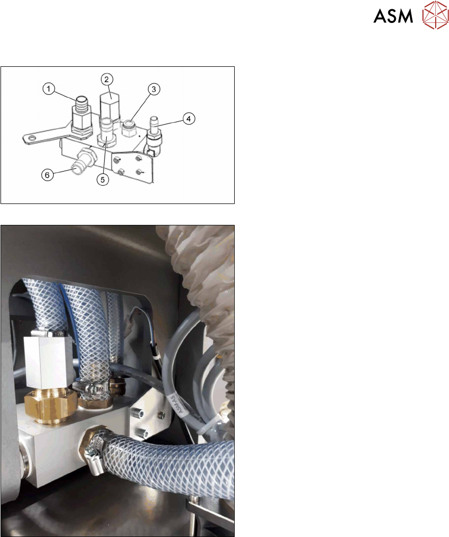
3.3.1 Installing the vacuum control valve
Fig.29: Vacuum control valve when installed
(SIPLACETX2iV1)
Fig.30: Vacuum control valve when installed
(SIPLACETX2V2)
► Remove the hose connector
N‑3/4‑P‑19(1) from the filter of the
vacuum pump.
CAUTION!
Seal all screwed connections with
Loctite55.
See also 3.1 "Sealing the Pneumatic
Screwed Connections" [}87]
.
► Screw the hose connector(1) to the left
side of the T piece3/4".
► Screw the double nipple3/4"(2) to the
right side of the T piece.
► Screw the vacuum control valve Becker
ST613‑0‑2 [03109300‑xx](3) into the T
piece.
3 Installation
3.3 Connecting the vacuum pump
Assembly Instructions / Montageanleitung SIPLACE TX2i V1 SIPLACE TX2 V2 Option Mixed-Mode 01/2019 97
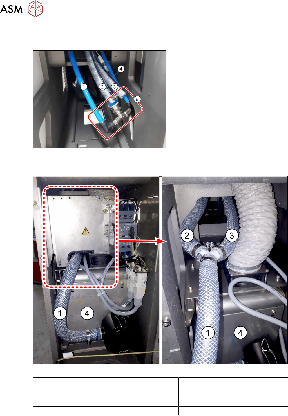
3.3.2 Connecting the vacuum pump (SIPLACE TX2i V1)
Fig.31: Connection on the pneumatics block R2
Fig.32: Converted pneumatics block
The pneumatics block R2 is located over the
vacuum pump.
1. Vacuum connection for holding circuit
2. Compressed air connection for holding
circuit
3. Compressed air to the placement cir-
cuit of head 1 and 2
4. Inlet compressed air from proportionate
valve 4.85 bar
5. Vacuum holding circuit
4x Camozzi hose to the compressed air
distributor
6. Hose vacuum pump [03113441‑xx]
► The operation with vacuum pump in
mixed mode requires that the hose
from the vacuum connection(1) is fitted
to the compressed air connection(2).
3 Installation
3.3 Connecting the vacuum pump
98 Assembly Instructions / Montageanleitung SIPLACE TX2i V1 SIPLACE TX2 V2 Option Mixed-Mode 01/2019
3.3.3 Connecting the vacuum pump (SIPLACE TX2 V2)
Overview of connections - initial situation compressed air operation
Fig.33: Connections for compressed air operation
1. Pneumatics hose from the proportional
valve (compressed air)
2. Fabric hose to the pneumatics block
Designation: compressed air/vacuum
→ 7-fold hose for compressed air hold-
ing circuit (both gantries)
3. Fabric hose to the pneumatics block
This fabric hose is only used when a
vacuum pump is installed.
4. Pneumatic hose to the pneumatics
block
(for placement circuit)
5. Upgrade kit 2 pneumatics
[03162637‑xx]
Overview of connections - initial situation vacuum operation
Fig.34: Connections for vacuum operation
1 Fabric hose to the vacuum pump 2 Fabric hose to the pneumatics block
Designation: compressed air/vacuum
→ for vacuum holding circuit (both
gantries)
3 Fabric hose to the pneumatics block 4 Vacuum pump