OM-1076-001.pdf - 第100页
B01 Shape Data (B01_10) 0107-001 2-74 Tg0502-PM-CL Fig. B153 Insp Condtn Normal Lead No. 1 Fig. B154 (9) Lead Group Insp Condtn Set a parameter to determine whether or not the positional data of the leads detected throug…
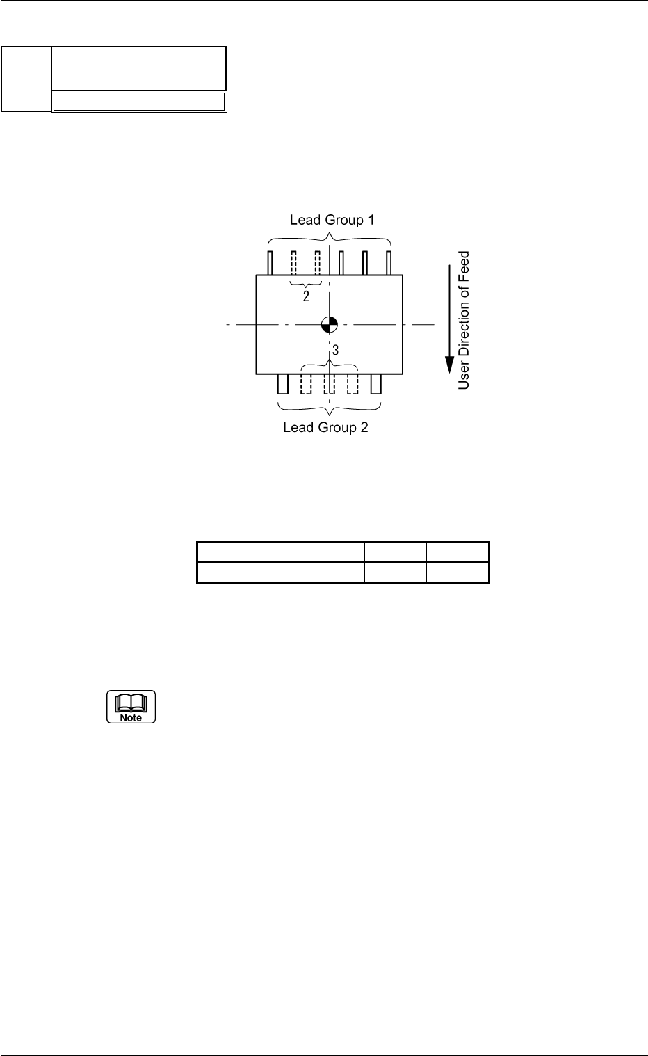
(8) Lead Group # of Missing Leads [pcs.]
Set the number of missing leads in the text box.
As for a heat sink, set the number of leads equivalent to the width of
the heat sink.
Table B17-1
Lead Group Data 1 2
Missing Leads 2 3
Unit: piece
Data Input Range: 0 to 255
Set this only when "Enable" is selected in the "Extended Setting" text box.
Applicable Components : IC (Simple), IC (Complex), Connector
(Simple), Connector (Complex), Other
Leaded (Simple), and Other Leaded
(Complex)
0206-003 2-73
Tg0502-PM-CL
B01 Shape Data (B01_10)
Fig. B152
# of Missing Leads [pcs.]
000
Lead
No.
1
Fig. B152-1
Top View of Component
B01 Shape Data (B01_10)
0107-001 2-74 Tg0502-PM-CL
Fig. B153
Insp Condtn
Normal
Lead
No.
1
Fig. B154
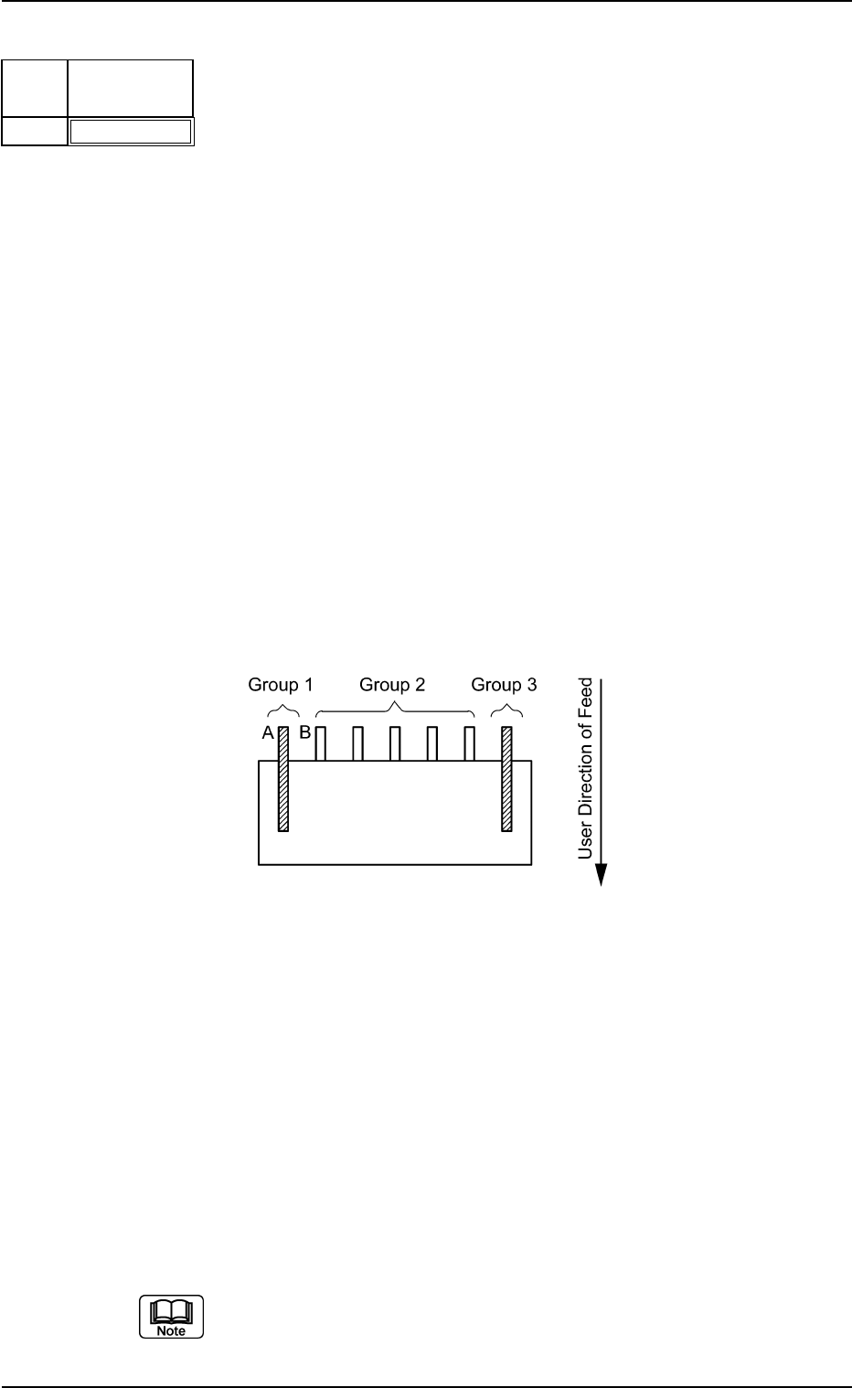
(9) Lead Group Insp Condtn
Set a parameter to determine whether or not the positional data of the
leads detected through recognition processing should be used to cal-
culate the position and angle of the component.
Select one of the following options.
Normal : When this is selected, the positional data of each
lead detected through recognition processing is
used to calculate the position and angle of the com-
ponent.
Select this except for a special component.
No Detection : When this is selected, the positional data of each
lead detected through recognition processing is not
used to calculate the position and angle of the com-
ponent.
Select this when there are similarly-shaped leads
not desired to calculate the position and angle of
the component near the leads desired to be used
for the calculation.
Applicable Components:
Connector (Complex)
Example: Connector
When the lead width and length of Lead Groups 1 and 3 are almost
the same as those of Lead Group 2 and the spacing between Lead
A of Lead Group 1 and Lead B of Lead Group 2 is almost the same
as the lead pitch of Lead Group 2, set parameters as follows in the
cases described below.
• To use Groups 1, 2, and 3 to position the component, set "Normal"
for Groups 1, 2, and 3.
• Not to use Groups 1 and 3 to position the component, set "Normal"
for Group 2 and "No Detection" for Groups 1 and 3.
Only the lead condition of Lead Group 2 gives an effect to the re-
sults of component positioning according to these settings.
Set these only when "Enable" is selected in the "Extended Setting" text
box.
B01 Shape Data (B01_10)
0107-001 2-75 Tg0502-PM-CL
Fig. B155
Top Posn (Long) Det [mm]
+99.999
Center Posn (Latl) Det [mm]
+99.999
Lead
No.
1
Fig. B156
Fig. B157
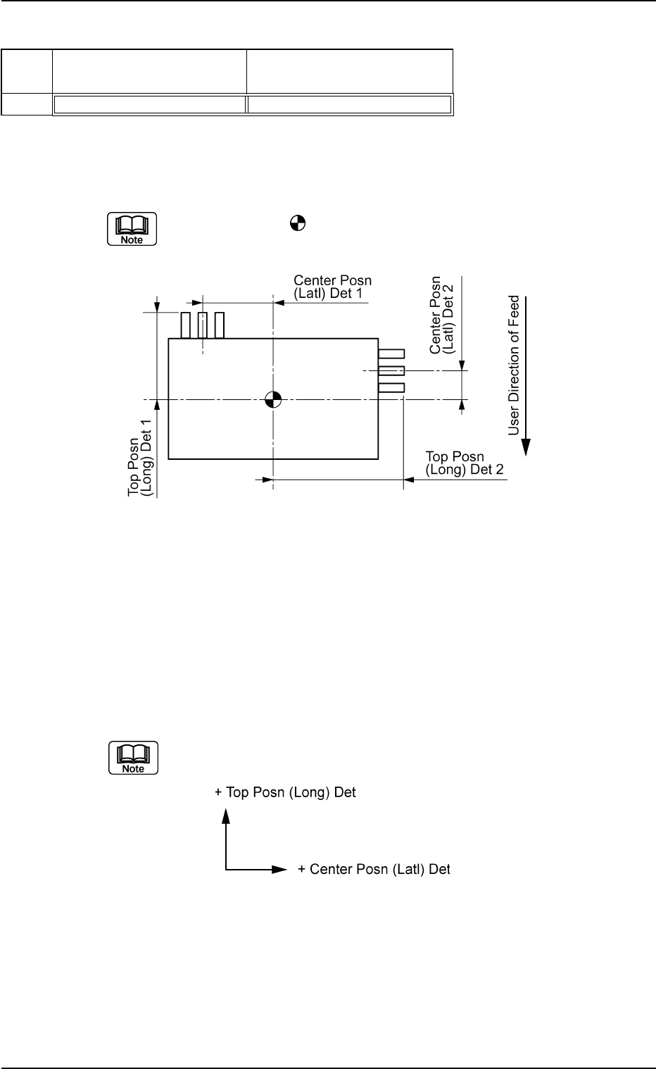
(10) Lead Group Center Posn (Latl) Det and Top Posn (Long) Det
Set the location of the lead groups in the text boxes.
Set the distance from the reference position where the outward length
is specified.
The center of the
mark is the reference position for outward length
setting.
Top View of Component
Unit: mm
Data Input Range
Center Position : −99.999 to +99.999
Prior Position : −99.999 to +99.999
Applicable Components : IC (Complex), Connector (Complex),
and Other Leaded (Complex)
(a) The coordinate system is as follows.
Note: The above-described coordinate system also rotates accord-
ing to the direction of a group.