OM-1076-001.pdf - 第115页
B02 Recognition Data (B02_03) 0206-003 2-88 Tg0502-PM-CL (B02_03) Recognition Level Set a recognition level for component checking. Set "1" in normal cases. Data Input Range : 00 to 99 Applicable Components : A…
B02 Recognition Data (B02_02)
0206-001 2-87-1 Tg0502-PM-CL
(B02_02) Recognition Data Set
Select one of the options to specify whether the recognition data re-
lated to each individual component shapes should be set automati-
cally or manually.
Auto : The defaults (determined in advance) are automatically
set.
Manual : Each recognition data can be set manually.
(a) Select "Auto" in normal cases.
(b) When the recognition data setting is set to "Auto", each data item is
automatically set as follows: For the set values, in the case of "Auto"
in the table, they are described in each data item.
Applicable Components : Applicable for all subjected components
Component
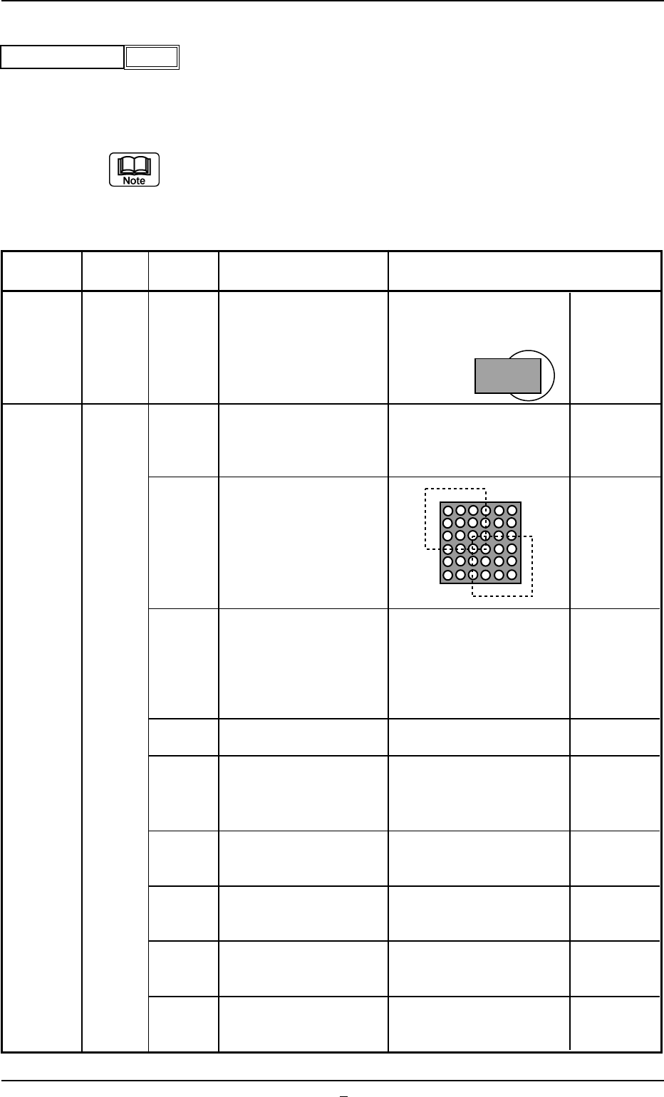
Cylindrical,
Deform IC Connector Other BGA/CSP
Shapes
Square,
(Complex)
Data Items
Deform
Recognition Level
(Simple)
1
Back Ltg Recog Algo or
Auto
Front Ltg Recog Algo
Lighting Pattern Auto
View Range Set Auto Selection
Mold Size Tolerance Set Auto
Outward length detn
Enable
(Auto)
Lead Width Detn Disable Disable
Lead Posn (Latl Dir) Detn
Enable Enable Enable
(Auto) (Auto) (Auto)
Lead Posn (Long Dir) Detn Disable
Electd pos Detn
Enable
(Auto)
Elected Size Detn Disable
Fig. B189
Auto
Recognition data set
Table B19-2
B02 Recognition Data (B02_03)
0206-003 2-88 Tg0502-PM-CL
(B02_03) Recognition Level
Set a recognition level for component checking.
Set "1" in normal cases.
Data Input Range: 00 to 99
Applicable Components : Applicable for all subjected components
(a) When "2" or a larger number is set, "Manual" should be
selected in the "Recognition data set" text box.
(b) Contents of Recognition Level "2" or Larger Number
Table B19-3
Component
Algorithm
Recognition
Description Sample Application
Shape
Level
Fig. B190
1
Recognition level
Leadless
Compo-
nents
(Cylindrical)
(Square)
(Deform)
Area Array
(BGA)
Corner
Grid
Pattern
Positioning can be made
based on only the recog-
nition result of two
corners.
(Size CR2012 or Smaller
One)
Positioning can only use
detected balls (Ball
presence/absence is not
checked).
Positioning can only use
detected balls in the two
windows (Ball presence
or absence is not
checked).
The way the component
angle, row, and column
are themselves detected
in the detected ball
candidates is different
from the standard way.
Applicable for X-shaped
ball arrangement
The brightness threshold
value is lowered when
the ball is detected.
The description com-
bines those for recogni-
tion levels11 and 2.
The description com-
bines those for recogni-
tion levels 11 and 3.
The description com-
bines those for recogni-
tion levels 11 and 4.
The description com-
bines those for recogni-
tion levels 11 and 5.
Positioning is possible
even when a nozzle has
come over the two corners.
This is effective for compo-
nents with spots that are
brighter than the balls on
the mold (except for balls).
2
2
3
4
5
11
12
13
14
15
0206-002 2-88-1 Tg0502-PM-CL
B02 Recognition Data (B02_03)
This mode is effective
when the lead ends are
not shaped rectangle.
This is effective for the
components having
rectangular electrodes
(QFN, etc.).
This is effective for the
components having
deform electrodes.
This is effective when the
lead ends are not shaped
rectangle.
This is effective for the
components having
rectangular electrodes.
This is effective for the
components having
deform electrodes.
Multiple
Pin Lead
(General
Purpose)
Leaded
Compo-
nents(IC)
(Connector)
(Other
Leaded)
Multiple
Pin Lead
(Stan-
dard)
The coarse recognition
mode (for specially
shaped leads) must be
used.
Use the coarse recogni-
tion mode for electrodes.
(The tilting of individual
electrodes is checked.)
Use the coarse recogni-
tion mode for electrodes.
(The tilting of individual
electrodes is not
checked.)
Use the coarse recogni-
tion mode for ordinary
leads.
It is reinforced to check
whether or not the leads
are located at the edges
for coarse recognition.
The coarse recognition
mode (for specially
shaped leads) must be
used.
The combination of
Recognition Levels 2 and
11 is applied.
Use the coarse recogni-
tion mode for electrodes.
(The tilting of individual
electrodes is checked.)
Use the coarse recogni-
tion mode for electrodes.
(The tilting of individual
electrodes is not
checked.)
Use the coarse recogni-
tion mode for ordinary
leads.
11
21
28
31
2
11
12
21
28
31
Table B19-4
Component
Algorithm
Recognition
Description Sample Application
Shape
Level