OM-1076-001.pdf - 第124页
0206-003 2-93 Tg0502-PM-CL B02 Recognition Data (B02_07), (B02_08) (B02_07) Mold Size T olerance Set Select the component size allowance from the following options. Manual : Select this to set arbitrary parameters in the…
(B02_06) View Range Set
Select the view range used in the recognition operation from the fol-
lowing options.
Auto Selection : "Large View" or "Small View" can be selected au-
tomatically according to the selected component.
Small View : Select this when small view (movable camera) is
to be used.
"Small View" can be used only for the component which satisfies
the following conditions 1 or 2.
(Conditions 1)
· [Outward Length X Direction + Pickup Pos Correction X
×
2]
=< 24 mm
· [Outward Length Y Direction + Pickup Pos Correction Y
×
2]
=< 18 mm
· [Component Thickness (t + Ut) ] =< 5 mm
(Conditions 2)
· [Outward Length X Direction + Pickup Pos Correction X
×
2]
=< 10 mm
· [Outward Length Y Direction + Pickup Pos Correction Y
×
2]
=< 10 mm
· [Component Thickness (t + Ut) ] =< 6.5 mm
If neither condition 1 nor condition 2 is satisfied, the Error
display appears.
Large View : Select this when large view (fixed camera) is
to be used.
Min View (Option) : Select this when large view (fixed camera) is
to be used.
(a) Select "Auto Selection" in normal cases.
(b) Set this only when "Manual" is selected in the "Recognition data set"
text box.
(c) For the Minimum View, the Compound Eye View (Option) setting is
required. Consult our marketing department or sales agency for de-
tails.
Applicable Components : Applicable for all subjected components
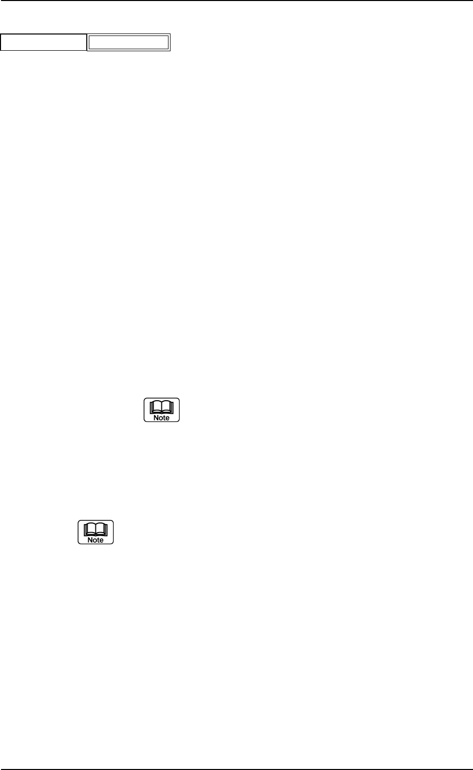
B02 Recognition Data (B02_06)
Fig. B199
Auto Selection
View range set
0206-003 2-92 Tg0502-PM-CL
0206-003 2-93 Tg0502-PM-CL
B02 Recognition Data (B02_07), (B02_08)
(B02_07) Mold Size Tolerance Set
Select the component size allowance from the following options.
Manual : Select this to set arbitrary parameters in the "Mold size
tolerance X" and "Mold size tolerance Y" text boxes.
Auto : Select this to automatically set parameters in the "Mold
size tolerance X" and "Mold size tolerance Y" text boxes.
The defaults are automatically set in the "Mold size toler-
ance X" and "Mold size tolerance Y" text boxes.
(a) Set this only when "Manual" is selected in the "Recognition data set"
text box.
(b) Normally, select "AUTO".
When "Auto" is set in the "Mold Size Tolerance Set" text box, the
value indicated in the "Mold Size tolerance" text box is used.
Applicable Components : Cylindrical, Square, and Deform
(Simple)
(B02_08) Mold Size Tolerance X [mm] and Y [mm]
When "Manual" is set in the "Mold Size Tolerance Set" text box, set
the tolerance value for the mold size.
Unit: mm
Data Input Range: 0 to 9.99
(a) When the dimensions described in the component approval drawing
are used for "Mold Size X" and "Mold Size Y", the tolerances might
not become the same (±). In this case, change mold dimensions X
and Y so that both tolerances are increased or decreased to equal
values.
(b) Set parameters only when "Manual" is selected in the "Recognition
data set" and "Mold size tol set" text boxes.
Applicable Components : Cylindrical, Square, and Deform
(Simple)
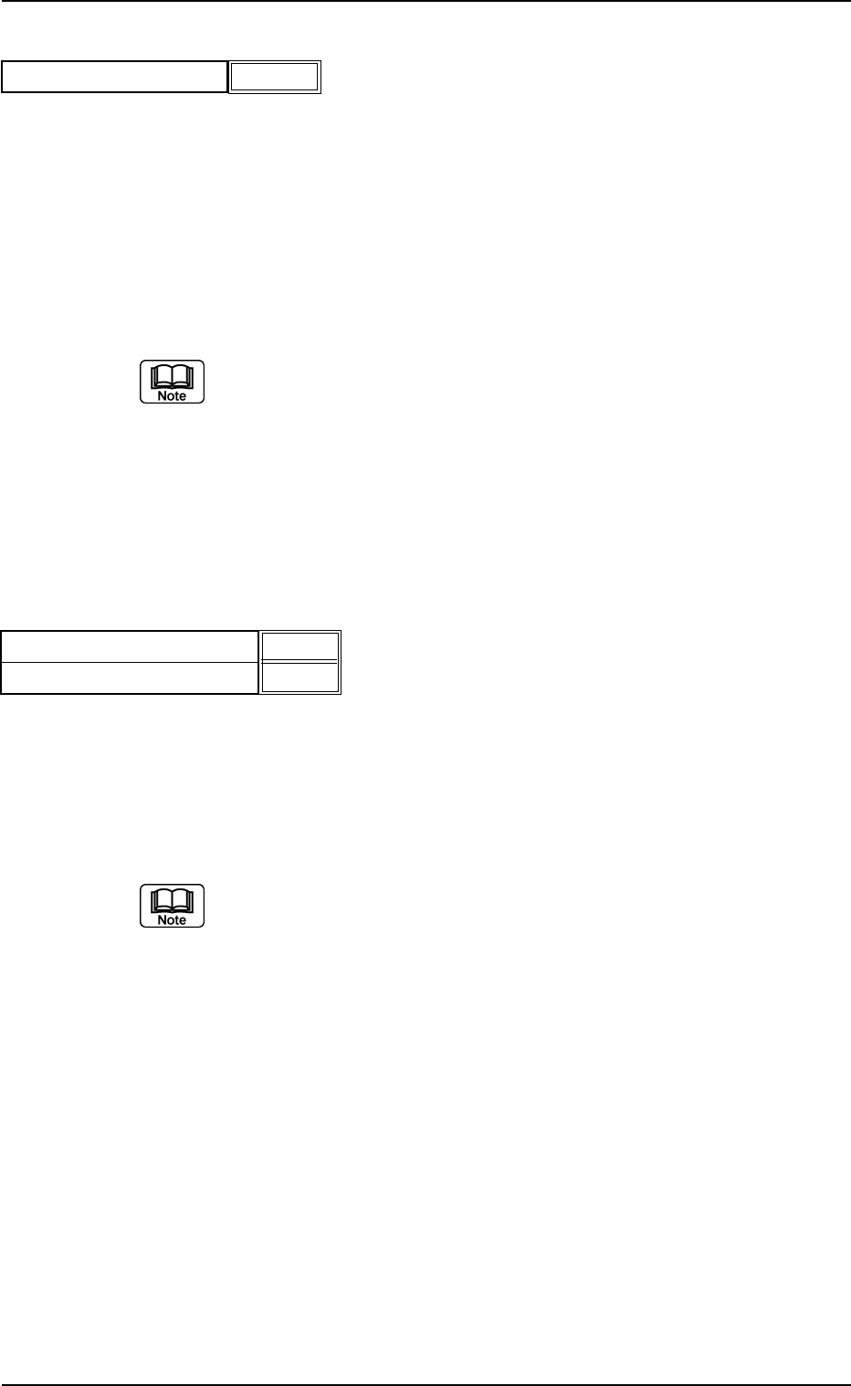
Fig. B200
Mold size tolerance set
Auto
Fig. B201
Mold size tolerance X [mm]
Mold size tolerance Y [mm]
0.20
0.20
(B02_09) Lead Width Detn/Lead Width Tol [mm]
Select whether or not the Lead Width Judgement is performed. If it is,
select the allowance from the following options.
Disable : Select this when the lead width determination
should not be made.
Enable (Auto) : Select this to automatically set the lead width toler-
ance according to the dimensional data of the leads.
Enable (Mnl) : Select this to arbitrarily set the lead width tolerance.
Unit: mm
Data Input Range: 0 to 9.99
(a) Set this only when "Manual" is set in the "Recognition data set" text
box.
(b) When "Enable (Auto)" is set in the "Lead width detn" text box, the
value indicated in the "Lead width tol [mm]" text box is used.
Applicable Components : IC (Simple), IC (Complex), Other
Leaded (Simple), and Other Leaded
(Complex)
0206-003 2-94
Tg0502-PM-CL
B02 Recognition Data (B02_09)
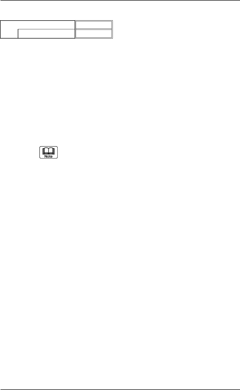
Fig. B202
Enable (Mnl)
0.30
Lead width detn
Lead width tol [mm]