OM-1076-001.pdf - 第128页
0206-003 2-97 Tg0502-PM-CL (B02_13) Electd Pos Detn/Electd Pos T ol [mm] Select whether or not the Electrical Contact Position Judgement is performed. If it is, select the allowance from the following options. Disable : …
0206-003 2-96 Tg0502-PM-CL
B02 Recognition Data (B02_12)
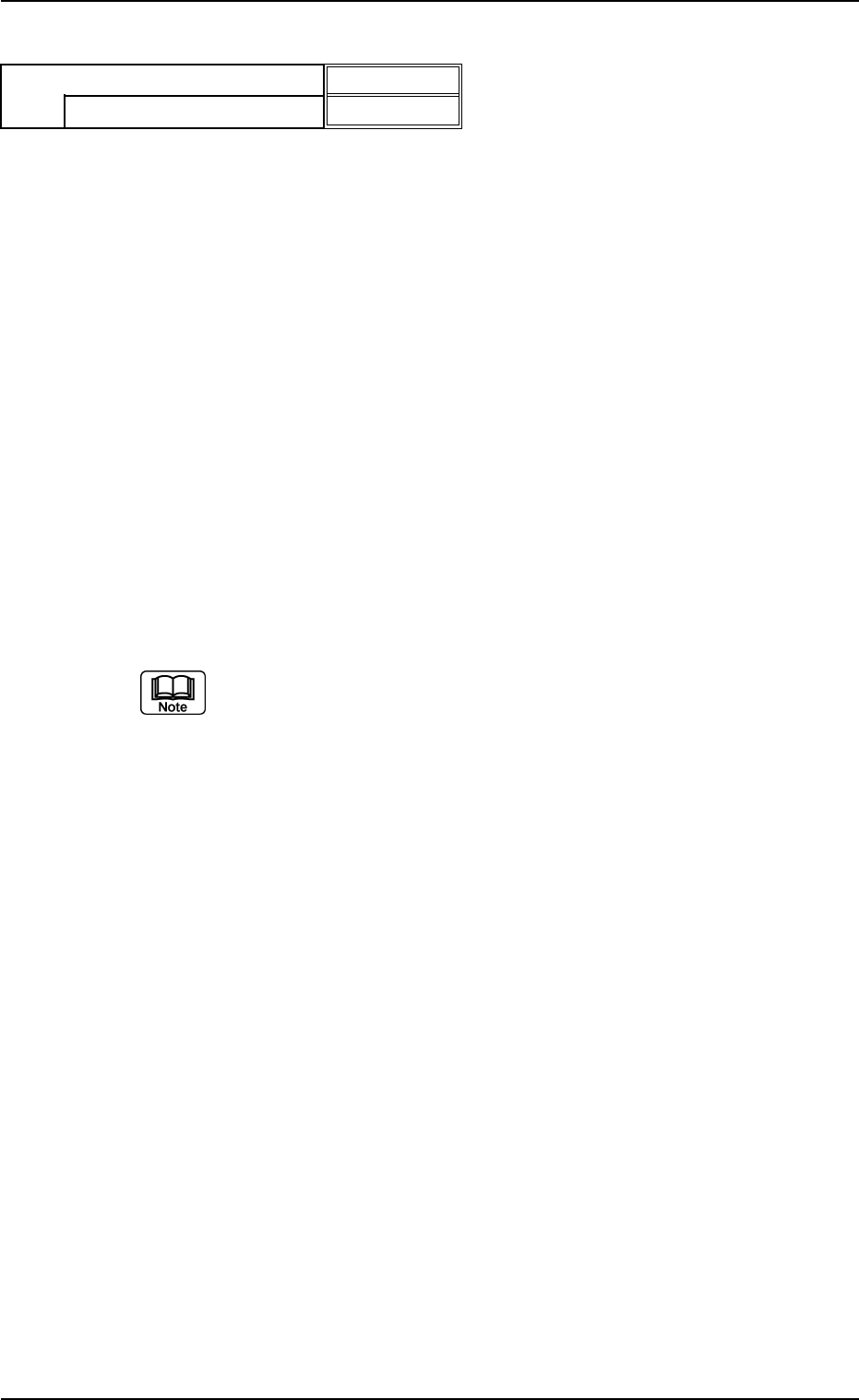
(B02_12) Outward length detn/Outward length tol [mm]
Select one of the following options to determine whether or not the
positional deviation of the lead group end line should be determined.
When "Enable (Auto)" or "Enable (Mnl)" is selected, the tolerance
must be specified.
Disable : Select this when the outward length should not be
determined.
Enable (Auto) : Select this to determine the outward length auto-
matically.
When this is selected, the default (automatically
specified value) is used.
Enable (Mnl) : Select this to determine the outward length manu-
ally.
The manually specified value is used as an out-
ward length tolerance.
Unit: mm
Data Input Range: 0 to 9.99
(a) To set a parameter, select "Manual" in the "Recog data set" text box.
(b) When "Enable (Auto)" is set in the "Outward length detn" text box, the
value indicated in the "Outward length tol [mm]" text box is used.
(c) As for ICs, it is required to set a parameter when "Gull Wing" or
"Straight" is selected in the "Type" text box of the label "Lead" in the
"Lead Data" tab sheet.
Applicable Components: Deform (Complex), IC (Simple), IC (Complex)
Fig. B204
Disable
0.00
Outward length detn
Outward length Tol [mm]
0206-003 2-97 Tg0502-PM-CL
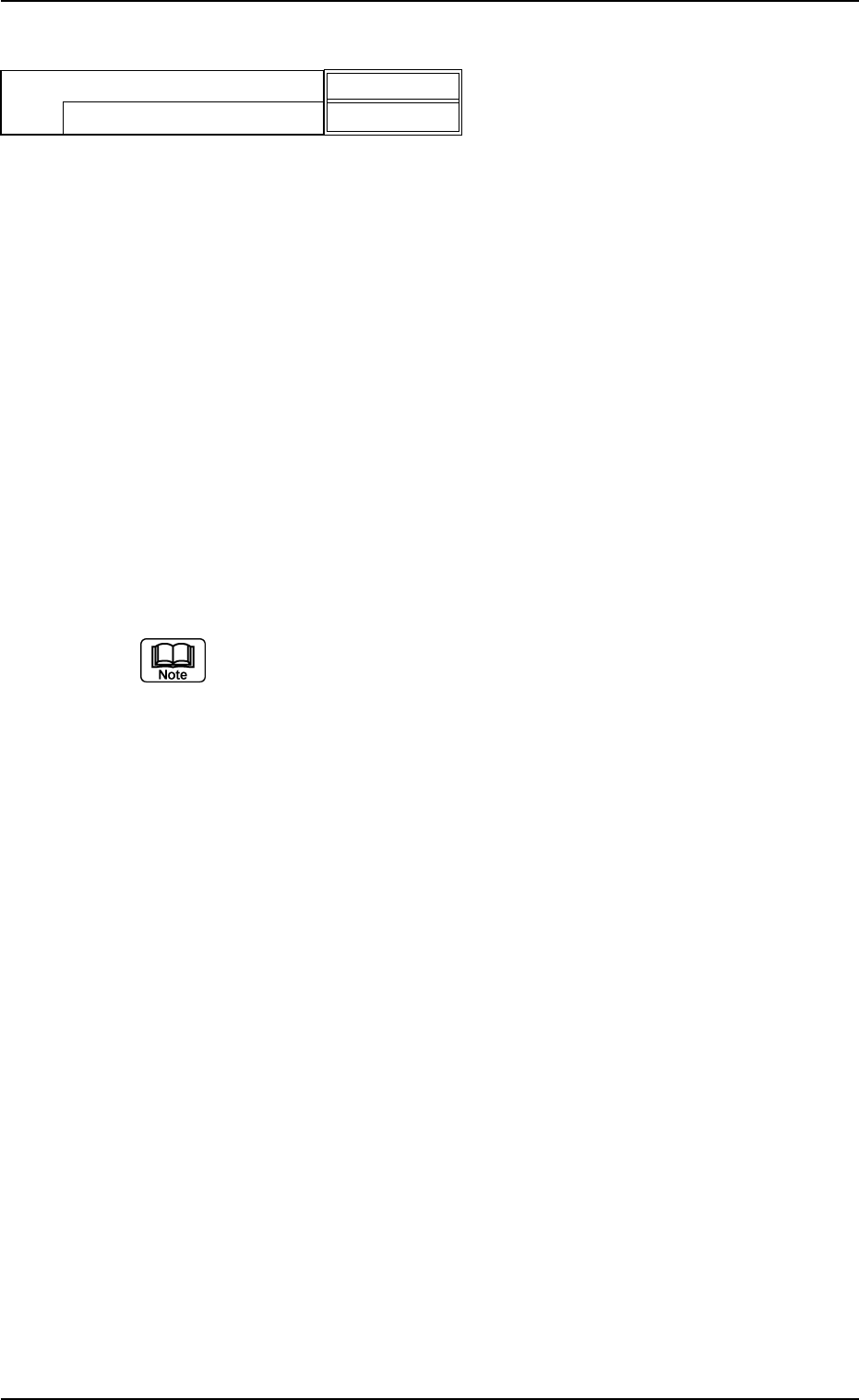
(B02_13) Electd Pos Detn/Electd Pos Tol [mm]
Select whether or not the Electrical Contact Position Judgement is
performed. If it is, select the allowance from the following options.
Disable : Select this when no electrode position determina-
tion is not to be made.
Enable (Auto) : Select this when the electrode position determi-
nation should be made. The default value which
has been automatically set is used for the elec-
trode position tolerance.
Enable (Mnl) : Select this when the electrode position determi-
nation should be made. The arbitrarily set value is
used for the electrode position tolerance.
Unit: mm
Data Input Range: 0 to 9.999
(a) Select this only when "Manual" is set in the "Recognition data set"
data box.
(b) When "Enable (Auto)" is set in the "Electd pos detn" text box, the
value indicated in the "Electd pos tol [mm]" text box is used.
Applicable Components: BGA/CSP
B02 Recognition Data (B02_13)
Fig. B205
Enable (Auto)
0.000
Electd pos detn
Electd pos tol [mm]
0206-003 2-98 Tg0502-PM-CL
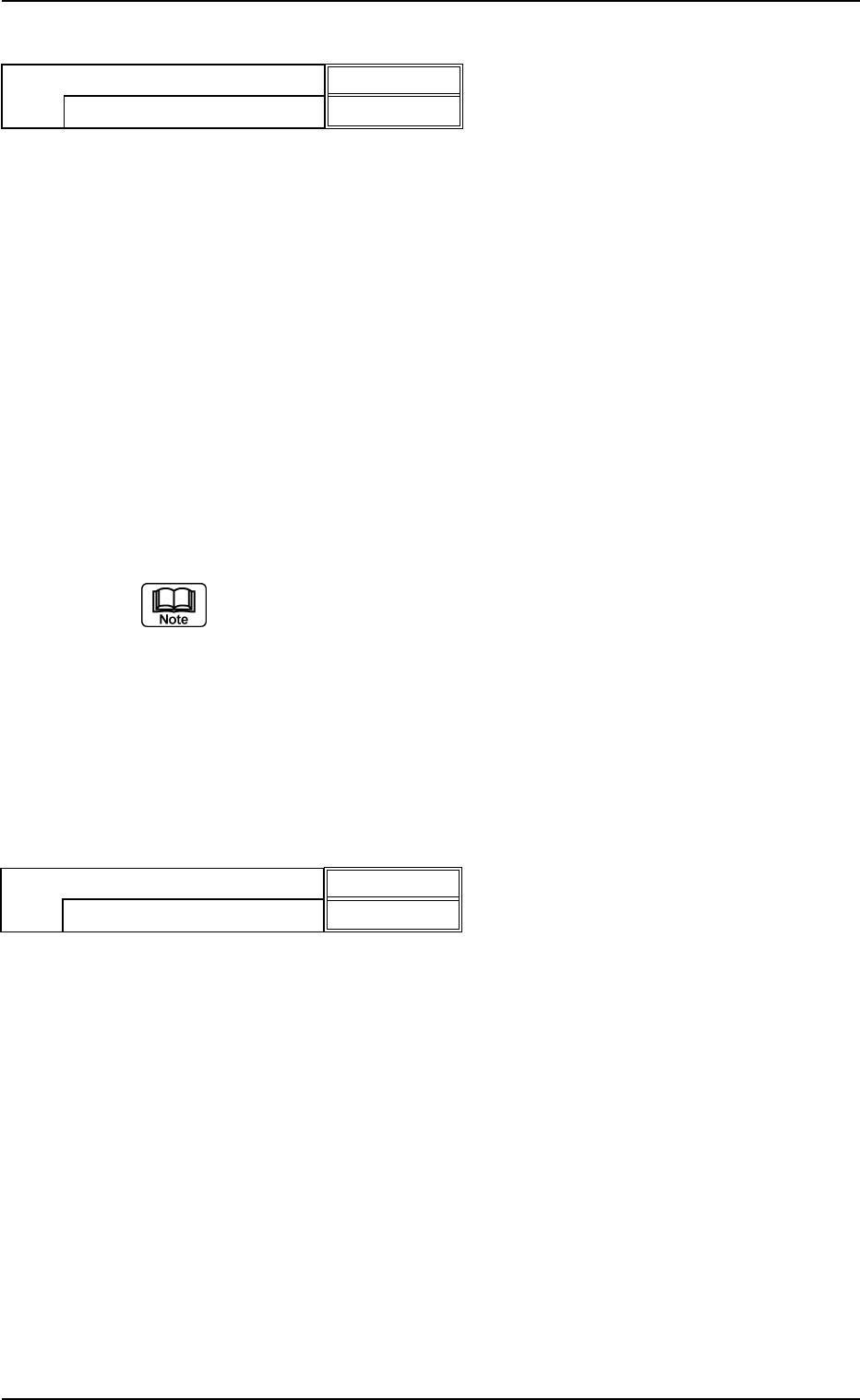
(B02_14) Electd Size Detn/Electd Size Tol [mm]
Select whether or not the Electrical Contact Size Judgement is per-
formed. If it is, select the allowance from the following options.
Disable : Select this when the electrode size determination
is not to be made.
Enable (Auto) : Select this when the electrode size determination
should be made. The automatically set default
value is used for the electrode size tolerance.
Enable (Mnl) : Select this when the electrode size determination
should be made. The arbitrary set value is used
for the electrode size tolerance.
Unit: mm
Data Input Range: 0 to 9.999
(a) Select this only when the "Manual" is set in the "Recognition data set"
data box.
(b) When "Enable (Auto)" is set in the "Electd size detn" text box, the
value indicated in the "Electd size tol [mm]" text box is used.
Applicable Components : BGA/CSP
(B02_15) Upper / Lower Surface Detn (Not Available)
Applicable Components : Square
B02 Recognition Data (B02_14), (B02_15)
Fig. B206
Enable (Auto)
0.000
Electd size detn
Electd size tol [mm]
Fig. B207
Enable
Bright
Upper / Lower surface detn
Cmpnt-Mounted surf image