OM-1076-001.pdf - 第131页
Fig. B214 2-Point Inspection • Sequence of Polarity Determination T op View of Component (Polarity Different by 180°) Fig. B21 1 (2) Inspection method Select one of the following options for the number of points to be in…
0206-002 2-99 Tg0502-PM-CL
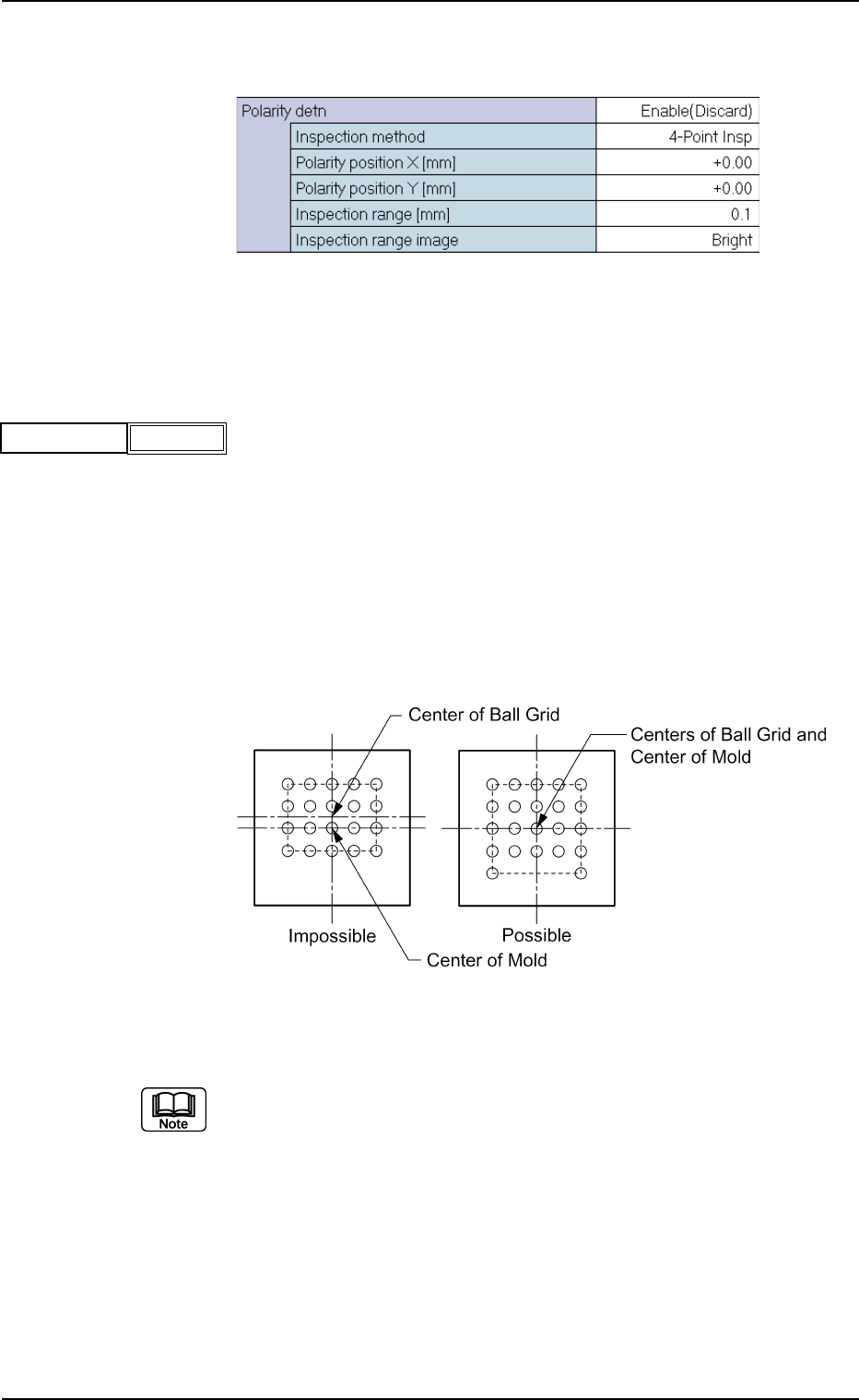
(B02_16) Polarity detn Data
Set the determination way for the component polarity (direction).
Fig. B208 Edit Window (Example)
Applicable Components : BGA/CSP
(1) Polarity detn
Select one of the following options to ascertain whether or not the
polarity determination function should be implemented.
Disable : Select when the polarity determination function is
not implemented.
Enable (Discard) : Select when the polarity has been checked and
found to be different, and is to be determined as
an error.
Enable (Placement) : Select when the recognition function is re-performed
according to the determined polarity after the po-
larity is checked and determined.
Top View of Component
Fig. B210
(a) When "Enable (Placement)" is selected, the recognition processing
time becomes twice or more than usual.
(b) When it is required to check whether or not a component has a polar-
ity (when components are not fed in the specified direction), "Enable
(Discard)" or "Enable (Placement)" must be set in the text box. The
machine performs the recognition operation after checking the polar-
ity.
(c) The following requirements must be met when "Enable (Discard)" or
"Enable (Placement)" is selected.
• With BGA/CSP components, the center of the ball grid should agree
with the center of the mold.
Fig. B209
Polarity detn
Disable
B02 Recognition Data (B02_16)
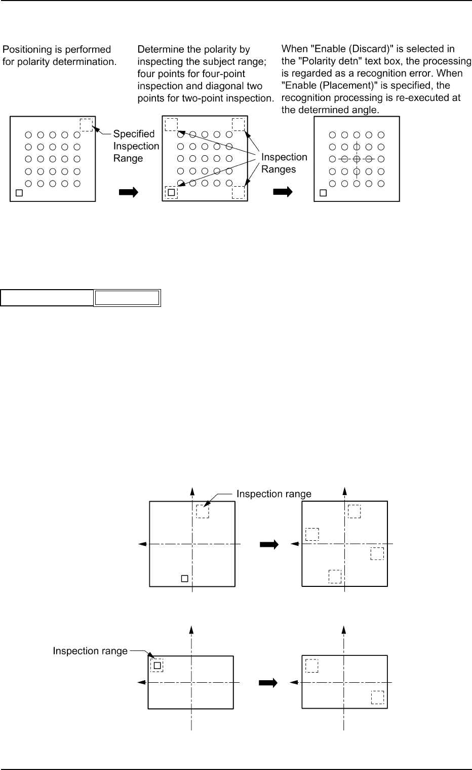
Fig. B214 2-Point Inspection
• Sequence of Polarity Determination
Top View of Component (Polarity Different by 180°)
Fig. B211
(2) Inspection method
Select one of the following options for the number of points to be in-
spected for polarity determination.
4-Point Insp : Inspect four points which overlap when each mold is
turned to an angle of 90
°, using the center of the mold
as the reference.
Select when the mold shape is square.
2-Point Insp : Inspect two points which are positioned diagonally when
the mold is turned through 180
°, using the center of
the mold as reference.
Select when the mold shape is rectangular.
Fig. B213 4-Point Inspection
0206-001 2-100
Tg0502-PM-CL
Fig. B212
Inspection method
4-Point Insp
B02 Recognition Data (B02_16)
0206-001 2-101 Tg0502-PM-CL
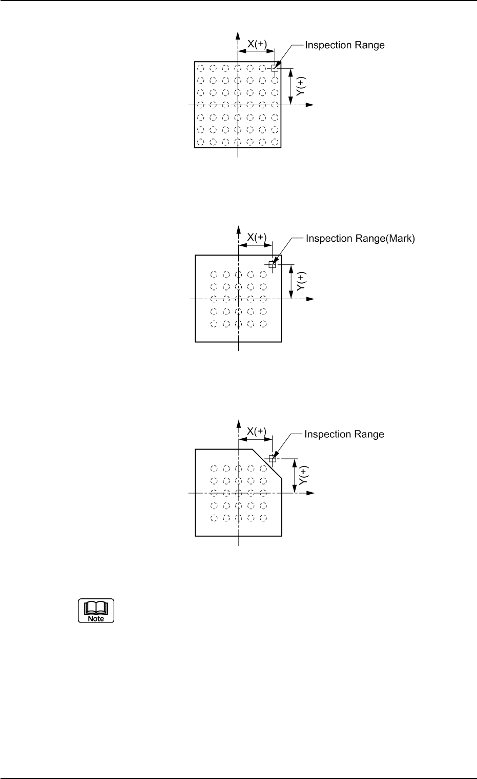
Example: Regarding the missing ball as a polarity
Top View of Component
Fig. B215
Example: Regarding the mark on the mold as a polarity
Top View of Component
Fig. B216
Example: Regarding the cutout of the mold as a polarity
Top View of Component
Fig. B217
(a) When the cutout on the mold is regarded as a polarity, it should lie
within the back lighting range. Therefore, the subjected mold sizes
are 18 × 18 mm or less.
(b) When the cutout on the mold is regarded as a polarity, use the follow-
ing settings.
Recognition Data Set : Manual
Ltg Pattern Designation: Manual
Back Ltg : - 80 % or - 60 %
Front Ltg (Up) : Std
Front Ltg (Mid) : Off
Front Ltg (Dn) : Off
B02 Recognition Data (B02_16)