OM-1076-001.pdf - 第149页
3.1 General Components (ICs excluded) 0107-001 3-10 Tg0502-PM-CL Fig. C8 Fig. C9 Fig. C10 Fig. C1 1 Fig. C12 (4) Examples of T aping (Specifications) The arrows in the figures represent the user direction of component fe…
3.1 General Components (ICs excluded)
0107-001 3-9 Tg0502-PM-CL
(3) Taping Specifications
15th and 16th cells are added in the component ID, representing
the taping specifications. Each character in the cells represents
the following.
Component ID: 15 16
15th Cell : The specified character represents the location
(direction) of leads.
L : This represents that leads are located on the left side
in the user direction of component feed.
R : This represents that leads are located on the right side
in the user direction of component feed.
F : User Direction of Component Feed
B : Backward Direction
16th Cell : The specified character represents the number or
thickness of leads.
1 : 1 pc.
2 : 2 pcs.
3 : 3 pcs.
B: Thick Lead
Example:(a)
TR1608-3B0SAN- L 1
This represents that there is a lead on the "L" side
in the user direction of component feed.
(b)
TR2915-4B0SAN- R B
This represents that there is a thick lead(s) on the
"R" side in the user direction of component feed.
3.1 General Components (ICs excluded)
0107-001 3-10 Tg0502-PM-CL
Fig. C8
Fig. C9
Fig. C10
Fig. C11
Fig. C12
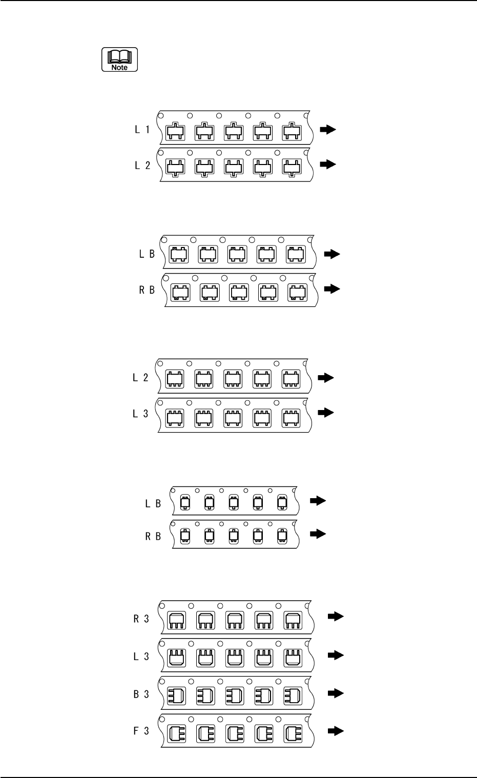
(4) Examples of Taping (Specifications)
The arrows in the figures represent the user direction of
component feed.
TR and DI with 3 Terminals
TR and DI with 4 Terminals
TR and DI with 5 Terminals
DI with 2 Terminals
PTR, CPTR, and MPTR
0107-001 3-11 Tg0502-PM-CL
3.1 General Components (ICs excluded)
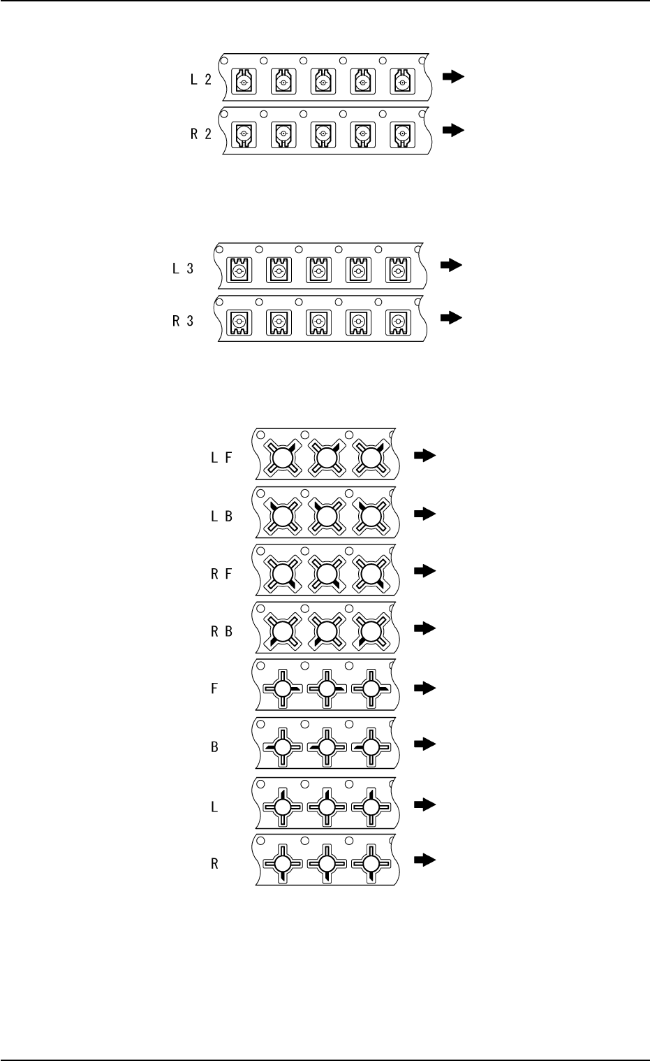
Fig. C13
Fig. C14
Fig. C15
Semi-Fixed Variable Resistor (2 terminals on one side)
Semi-Fixed Variable Resistor and TC (3 terminals on one
side)
HEMT