OM-1076-001.pdf - 第167页
3.1.2 Square Components Measure the dimensions (*1 through *12) in the figures. (1), (2), (3), and (4) in the figure correspond relatively to "Corner 1", "Cor- ner 2", "Corner 3", and "…
3. Measurement of Component Dimensions
Component dimensions must be measured according to the recognized
shape of each component.
Fill in the measured values on the individual data sheets.
(a) The measured values (dimensions) can be referred to when similar-
shaped components must be selected from the standard component
library.
(b) The measured values can also be referred to when new component
library must be created.
3.1 Leadless Components
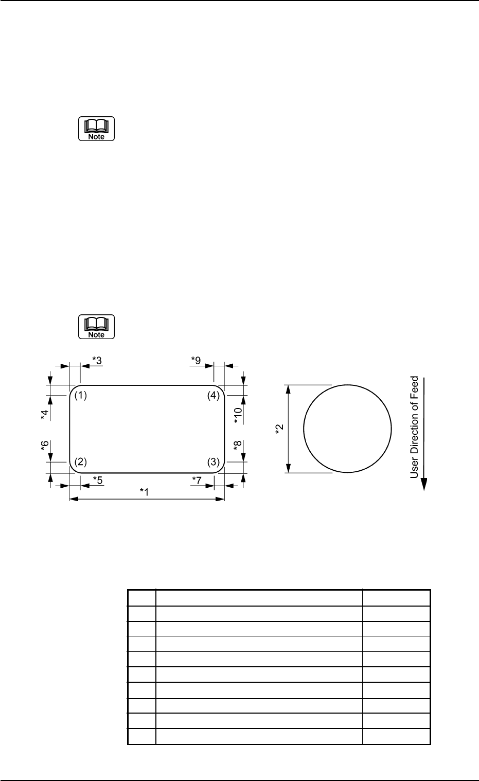
3.1.1 Cylindrical Components
Measures the dimensions (*1 through *10) in the figures.
(1), (2), (3), and (4) in the figure correspond relatively to "Corner 1", "Cor-
ner 2", "Corner 3", and "Corner 4" in the corner data.
Individual Data Sheet (Cylindrical)
Minimum Unit: 0.01 mm
*1 Mold Size X (Horizontal)
*2 Mold Size Y (Vertical)
*3 Corner 1 Dim X
*4 Corner 1 Dim Y
*5 Corner 2 Dim X
*6 Corner 2 Dim Y
*7 Corner 3 Dim X
*8 Corner 3 Dim Y
*9 Corner 4 Dim X
*10 Corner 4 Dim Y
3. Measurement of Component Dimensions
0107-001 4-9 Tg0502-PM-CL
Fig. D20
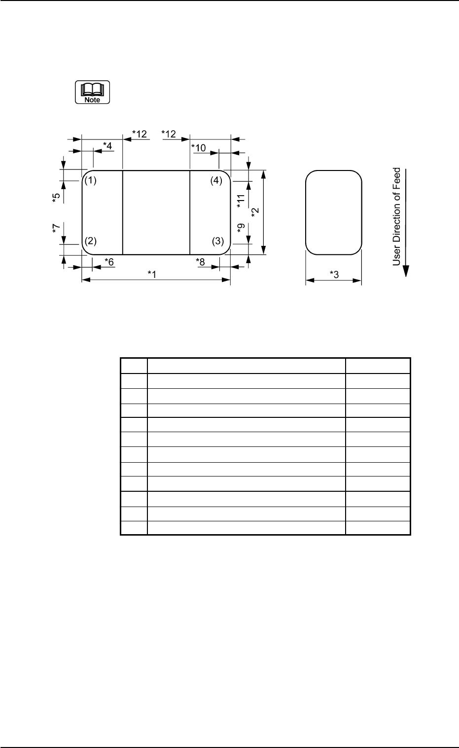
3.1.2 Square Components
Measure the dimensions (*1 through *12) in the figures.
(1), (2), (3), and (4) in the figure correspond relatively to "Corner 1", "Cor-
ner 2", "Corner 3", and "Corner 4" in the corner data.
Individual Data Sheet (Square)
Minimum Unit: 0.01 mm
*1 Mold Size X (Horizontal)
*2 Mold Size Y (Vertical)
*3 Mold Size t (Thickness) [T (Thickness)]
*4 Corner 1 Dim X
*5 Corner 1 Dim Y
*6 Corner 2 Dim X
*7 Corner 2 Dim Y
*8 Corner 3 Dim X
*9 Corner 3 Dim Y
*10 Corner 4 Dim X
*11 Corner 4 Dim Y
*12 Elctd Size
3.1 Leadless Components
0107-001 4-10 Tg0502-PM-CL
Fig. D21
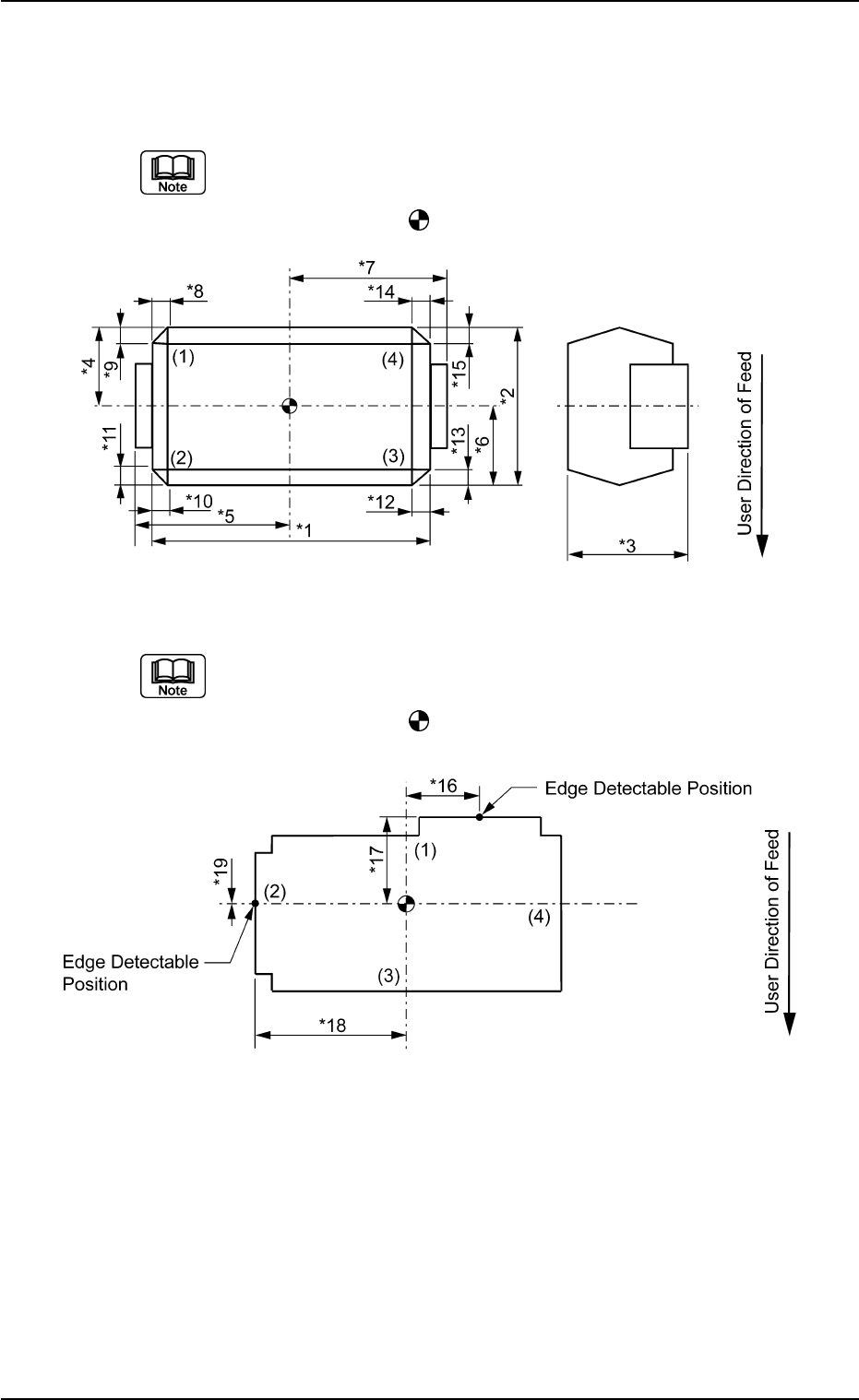
3.1.3 Deform (Simple) Components
Measure the dimensions (*1 through *19) in the figures.
(a) (1), (2), (3), and (4) in the figure correspond relatively to "Corner 1",
"Corner 2", "Corner 3", and "Corner 4" in the corner data.
(b) The center of the
mark indicates the center of the mold.
(a) (1), (2), (3), and (4) in the figure correspond relatively to "Corner 1",
"Corner 2", "Corner 3", and "Corner 4" in the corner data.
(b) The center of the
mark indicates the center of the mold.
0107-001 4-11 Tg0502-PM-CL
3.1 Leadless Components
Fig. D22
Fig. D23