OM-1076-001.pdf - 第169页
3.1 Leadless Components 0107-001 4-12 Tg0502-PM-CL Individual Data Sheet (Deform: Simple Shape) Minimum Unit: 0.01 mm *1 Mold Size X (Horizontal) *2 Mold Size Y (V ertical) *3 Mold Size t (Thickness) [T (Thickness)] *4 O…
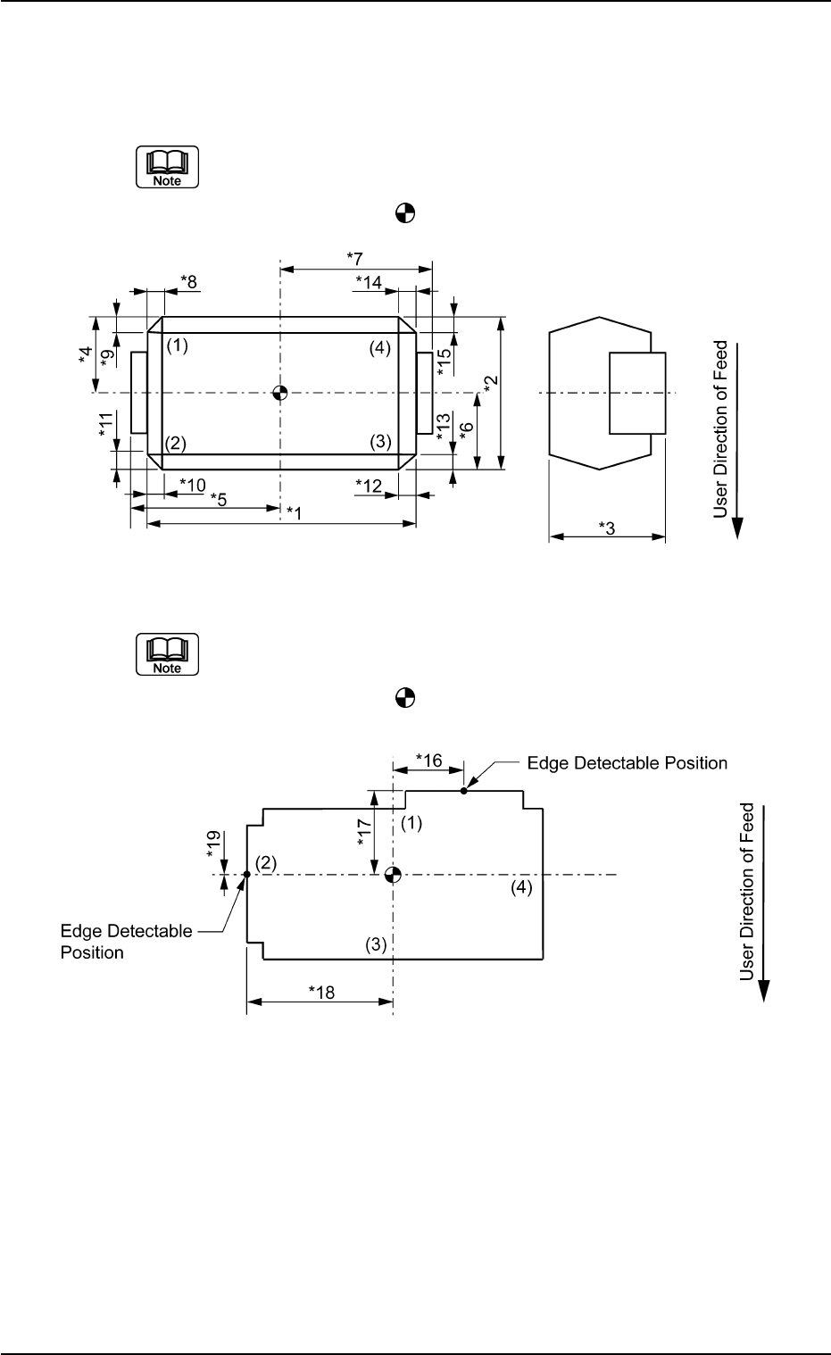
3.1.3 Deform (Simple) Components
Measure the dimensions (*1 through *19) in the figures.
(a) (1), (2), (3), and (4) in the figure correspond relatively to "Corner 1",
"Corner 2", "Corner 3", and "Corner 4" in the corner data.
(b) The center of the
mark indicates the center of the mold.
(a) (1), (2), (3), and (4) in the figure correspond relatively to "Corner 1",
"Corner 2", "Corner 3", and "Corner 4" in the corner data.
(b) The center of the
mark indicates the center of the mold.
0107-001 4-11 Tg0502-PM-CL
3.1 Leadless Components
Fig. D22
Fig. D23
3.1 Leadless Components
0107-001 4-12 Tg0502-PM-CL
Individual Data Sheet (Deform: Simple Shape)
Minimum Unit: 0.01 mm
*1 Mold Size X (Horizontal)
*2 Mold Size Y (Vertical)
*3 Mold Size t (Thickness) [T (Thickness)]
*4 Outward Length 1
*5 Outward Length 2
*6 Outward Length 3
*7 Outward Length 4
*8 Corner 1 Dim X
*9 Corner 1 Dim Y
*10 Corner 2 Dim X
*11 Corner 2 Dim Y
*12 Corner 3 Dim X
*13 Corner 3 Dim Y
*14 Corner 4 Dim X
*15 Corner 4 Dim Y
*16 Edge Data 1 Detection Posn X
*17 Edge Data 1 Detection Posn Y
*18 Edge Data 2 Detection Posn X
*19 Edge Data 2 Detection Posn Y
0206-002 4-13 Tg0502-PM-CL
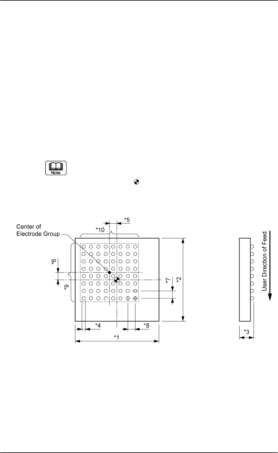
3.2 Area Array Components
Fig. D24
3.2 Area Array Components
3.2.1 BGA/CSP Components
Measure the dimensions (*1 through *10) in the figure below.
When a component has several electrode groups, set "Enable" in the
"Extended setting" text box and measure the dimensions (*5 through
*10) for Electrode Groups 2 through 6.
As for components with missing electrodes, set "Enable" in the "Ex-
tended setting" text box and the number of missing blocks in the "# of
Missing Electrodes" text box. After that, measure the dimensions (*11
through *14) in the figure.
When there are several missing blocks, measure the dimensions (*11
through *14) for Missing Electrodes 2, 3, and so on.
(Up to 40 blocks can be specified as electrode-missing blocks.)
(a) The figure shows the top view (no ball side) of the component and is
an example of "# of Electrode Groups = 1".
(b) The center of the mark is the reference point of the component.
(In normal cases, the reference point is located at the center of the
mold.)