OM-1076-001.pdf - 第32页
Set the "Selected Nozzle #1" to be used for component pick-up. The nozzles are distinguished by the differences in end size, shape, length, etc., and managed by using the nozzle IDs. (1) Nozzle ID Set the nozzl…
A02 Control Data
A02 Control Data
0111-002 2-13 Tg0502-PM-CL
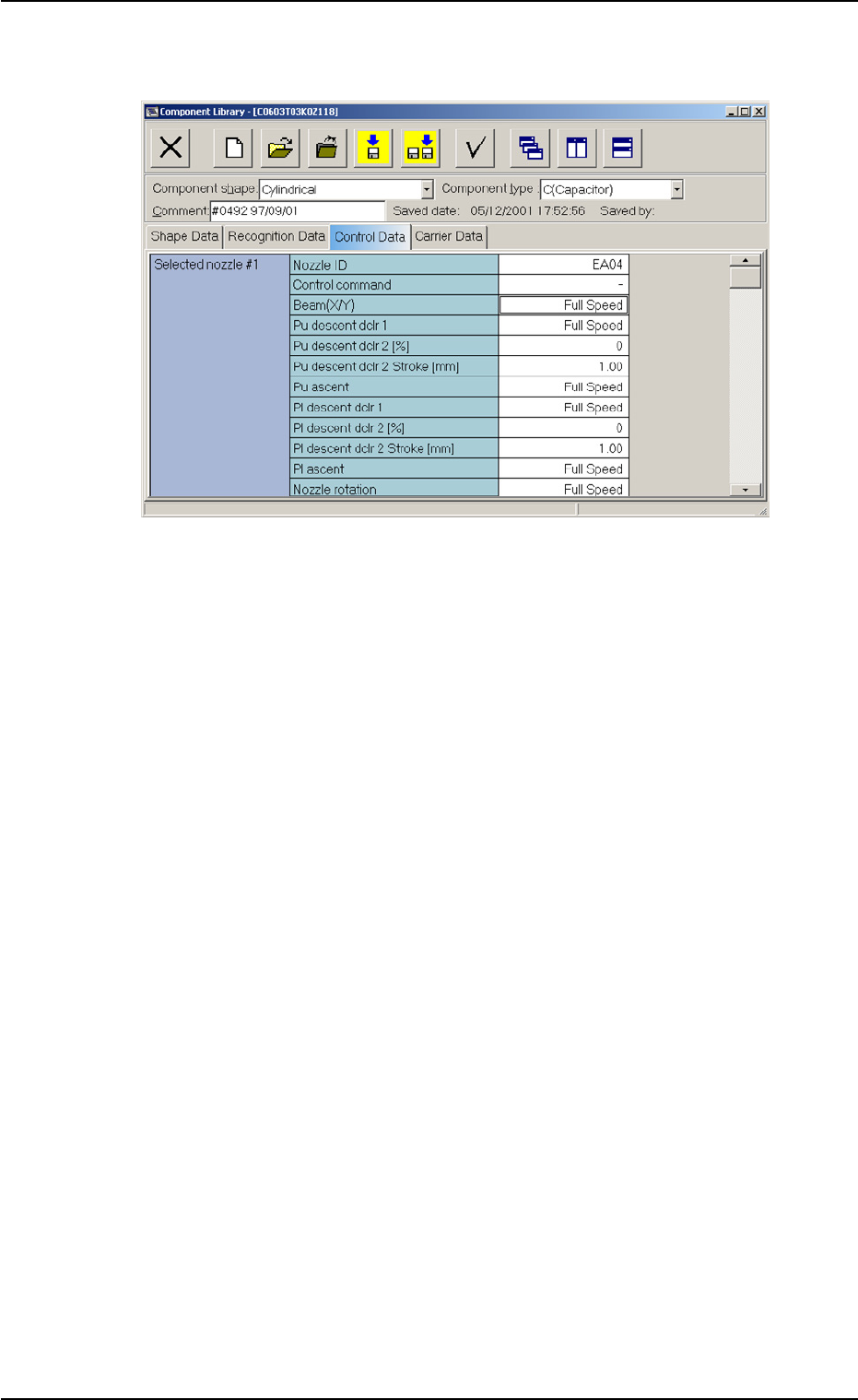
Fig. B9 Edit Window (Example) for Cylindrical Components
Set the "Selected Nozzle #1" to be used for component pick-up.
The nozzles are distinguished by the differences in end size, shape, length,
etc., and managed by using the nozzle IDs.
(1) Nozzle ID
Set the nozzle ID for the nozzle to be used.
(2) Control Command
Set a parameter to determine whether or not this nozzle should be
used.
Select one of the following options.
−−
−−
− : Select this when this nozzle is used.
S: Select this when this nozzle is not used.
(3) Beam (X/Y)
Select one of the following options to designate the rate of the X/Y
beam speed reduction during component pick-up.
Full Speed 10% Decr 20% Decr 30% Decr 40% Decr
50% Decr 60% Decr 70% Decr 80% Decr 90% Decr
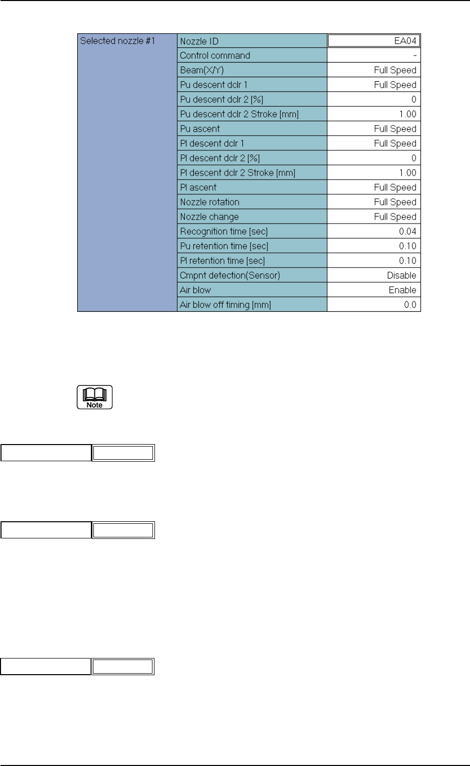
(A02_01) Selected nozzle #1
A02 Control Data (A02_01)
0111-002 2-14 Tg0502-PM-CL
Fig. B10 Edit Window (Example) for Cylindrical Components
Fig.B11
Nozzle ID
Fig.B12
Control command
Fig.B13
Beam(X/Y) Full Speed
(4) Pu Descent Dclr 1
Select one of the following options to designate the rate of the nozzle
descending speed reduction for pick-up.
Full Speed 10% Decr 20% Decr 30% Decr 40% Decr
50% Decr 60% Decr 70% Decr 80% Decr 90% Decr
(a) The descending motion starts from the pass line (lower or upper pass
line).
When a parameter is set in the "Dclr 2 Stroke" data box, the X/Y
beam descends to the bottom position of the stroke.
(b) The lower pass line is the lowest level of the X/Y beam movement
when the thickness of a previously-placed component (already-placed
component) is 6.5 mm or less.
The upper pass line is the lowest level of the X/Y beam movement
when the thickness of a previously-placed component is more than
6.5 mm. (Only in the placement PCB area)
(5) Pu Descent Dclr 2 [%]
Set a parameter to designate the rate of the speed reduction while the
X/Y beam is descending to the bottom of the stroke remaining.
Unit: %
Data Input Range: 0 to 99
(a) By making the X/Y beam descend at a very low speed for the remain-
der of the stroke (down to the pick-up lower limit), delicate compo-
nents pick-ups can be made in stable conditions.
The set parameter becomes valid only when it is larger than the rate
set in the "Dclr 1" data box.
(b) In the following case, the X/Y beam only descends according to the
parameter in the "Pu descent dclr 1" without making the two-step
speed reduction.
Pu Descent Dclr 2 =< Pu Descent Dclr 1
A02 Control Data (A02_01)
0206-002 2-15 Tg0502-PM-CL
Pu descent dclr 2 [%]
0
Fig.B15
Fig.B14
Pu descent dclr 1
Full Speed