OM-1076-001.pdf - 第43页
(A02_07) Placement Level [mm] Set the nozzle descent level for component placement, based on the component placement surface. Unit: mm Data Input Range : − 9.99 to + 9.99 (a) The nozzle descent level for component placem…
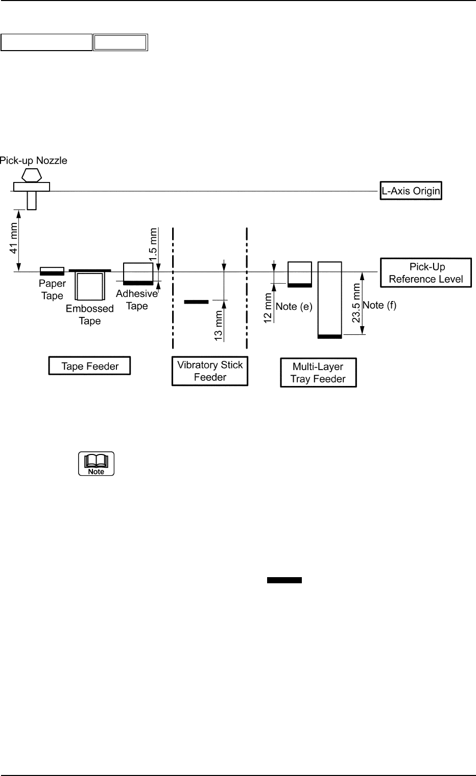
(A02_06) Pickup Level [mm]
Set a parameter to adjust the head descending level for component
pick-up.
Unit: mm
Data Input Range: −99.99 to +99.99
A02 Control Data (A02_06)
0107-001 2-23 Tg0502-PM-CL
Fig.B37
Pickup level [mm]
−99.99
Fig. B38
(a) When an embossed tape is used, a gap may be left between the
head and the packaged component, depending on the relation be-
tween the depth of the cavity and the thickness of the component in
the cavity. In that event, set a parameter in the data box to adjust the
head descending stroke.
(b) To increase the stroke for component pick-up (to make the head de-
scend further), set a parameter with a "+" sign.
(c) Consider the thickness (t) of the components (the distance from the
lower surface references ( ) shown in the figure) except for the
embossed tape and figure out the pick-up level. (Various groups of
offset data must also be taken into consideration separately).
(d) Actual operation range may be regulated (differ from the set values)
due to the control of the machine.
(e) Maximum Thickness of Tray at Pull-out to Upper Chute
: Max. 16.5 mm
(f) Maximum Thickness of Tray at Pull-out to Lower Chute (Option)
: Max. 28 mm
Side View
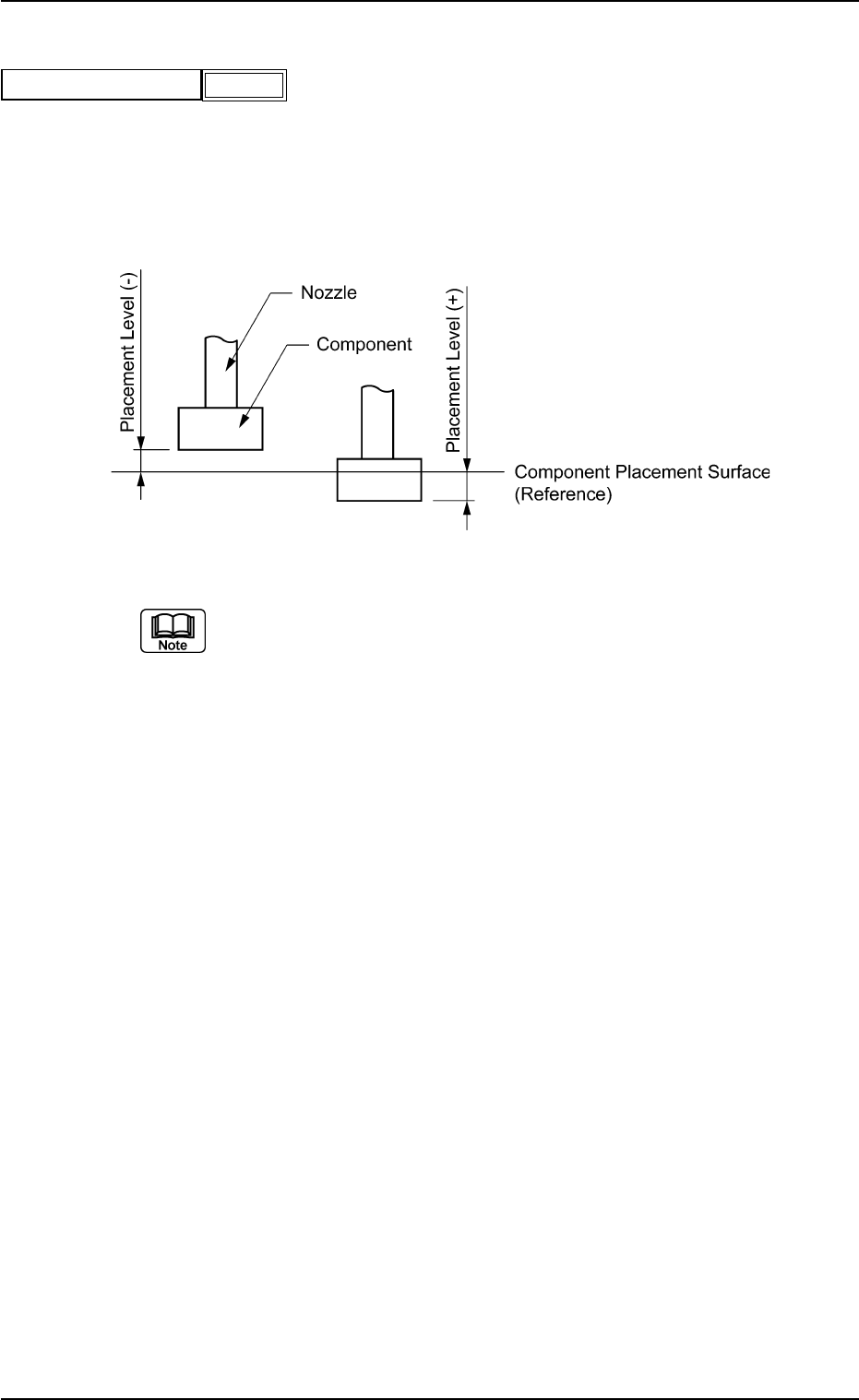
(A02_07) Placement Level [mm]
Set the nozzle descent level for component placement, based on the
component placement surface.
Unit: mm
Data Input Range: −9.99 to +9.99
(a) The nozzle descent level for component placement is controlled ac-
cording to the parameter set in the "t" (component thickness) text box
of the label "Mold Size" in "Shape Data". However, it can be changed
deliberately by setting a parameter in this text box.
In normal cases, a value with "+" sign must be entered to avoid the
warpage (sagging) of a PCB.
(b) Enter a plus (+) value to set the nozzle descent level lower than the
component placement surface for component placement.
(c) Actual operating range may be regulated (different from the set value)
due to the control of the machine.
A02 Control Data (A02_07)
0107-001 2-24 Tg0502-PM-CL
Fig. B39
Placement level [mm]
+0.30
Fig. B40
A02 Control Data (A02_08)
0107-001 2-25 Tg0502-PM-CL
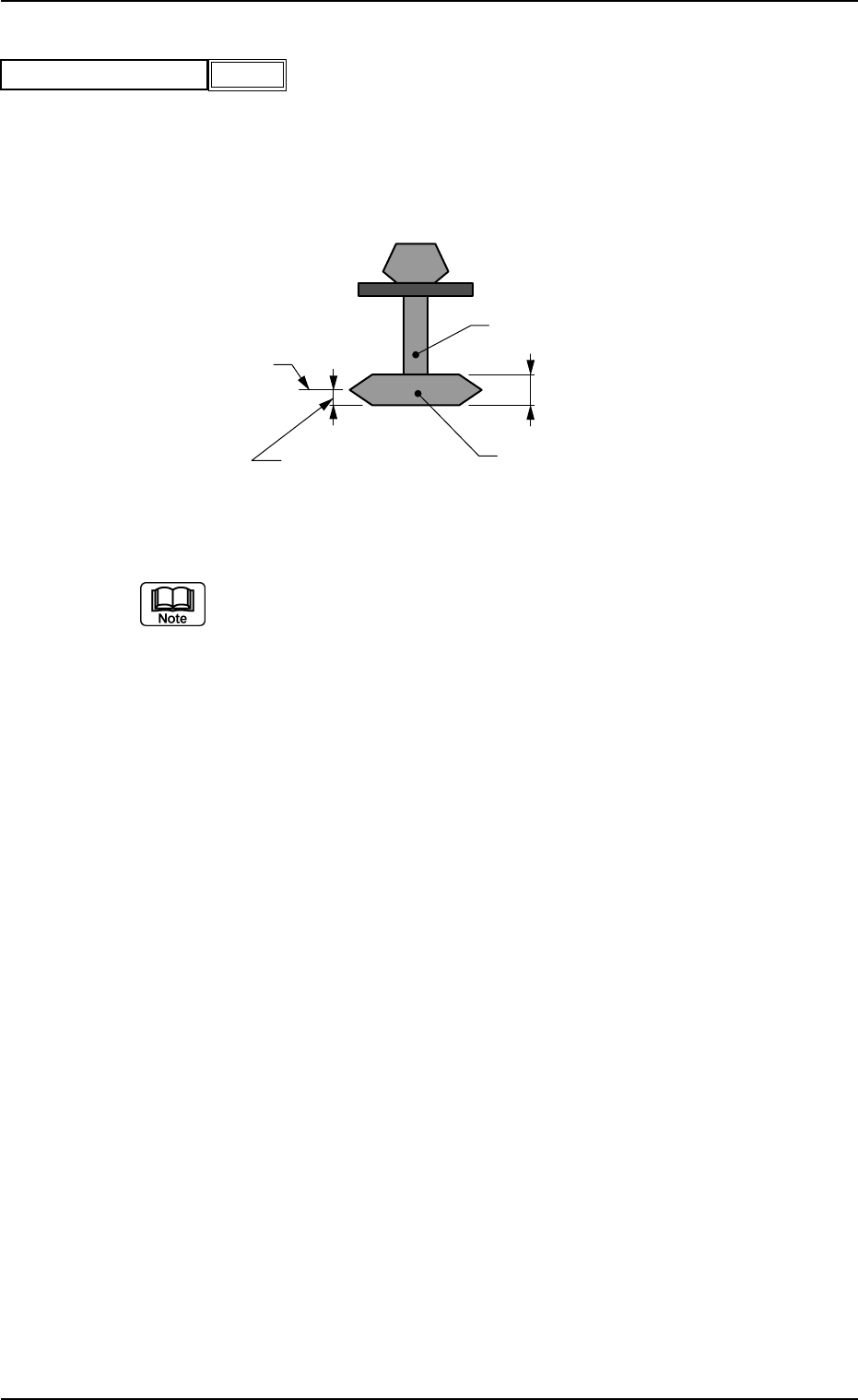
(A02_08) Focus Adjustment [mm]
Set the focus level when a component is recognized.
Unit: mm
Data Input Range: −99.99 to +99.99
(a) Actual operation range may be regulated (differ from the set values)
due to the control of the machine.
(b) In normal cases, the height level for component recognition is deter-
mined according to the parameter set in the "t" data box of the label
"Mold size". However, when a spot regarded as a target to be recog-
nized deviates from the focus point due to the shape of a component,
the set parameter can be used to correct the deviation.
(c) When the recognition target deviates from the focus point as shown
in the figure, enter the dimension (A) with "+" sign in the data box.
When a value with "+" sign is entered, the head will descend further
(as much as the set value) than the normal stroke and the photo-
image of the component is taken for component recognition. When
the parameter set in the "t" data box of the label "Mold size" can be
used as the level for component recognition, "0" (zero) must be set in
this data box.
Nozzle
Component Thickness (t)
Component
Side View
A (Focus Adjustment)
Focus Level
Fig.B41
Focus adjustment [mm]
−99.99
Fig. B42