OM-1076-001.pdf - 第47页
A03 Carrier Data (A03_01) Carrier Data (T ape) (1) T ype Select one of the following options as a type of a component carrier . Paper Embossed Adhesive Vibratory Stick T ray No types other than the above are used in TIM-…

A02 Control Data (A02_10)
0111-002 2-27 Tg0502-PM-CL
(A02_10) Error Process 2
The set parameter is used to monitor continuous pick-up errors (an
error caused continuously with a component being picked up) caused
due to component recognition error. The machine stops in an error
condition according to the number of error times. Set the number of
continuous component recognition errors in this data box.
Data Input Range: 1 to 9
1 : The machine stops in an error condition after a component recog-
nition error is detected once.
2 : The machine stops in an error condition after a component recog-
nition error is detected continuously twice on the same feeder.
n : The machine stops in an error condition after a component recog-
nition error is detected continuously "n" times on the same feeder.
(a) Recommended Data
Tape Component : 9
Components in Tray or Stick Feeder : 1
A pick-up error in the tray or vibration stick component might develop
into successive pick-up errors and cause interference with pick-up
nozzle. Therefore, we recommend stopping the machine when the
error is first detected.
(b) When the alternate function is activated, the set parameter becomes
one of the requirements for the alternate operation start.
Fig.B44
Error process 2
1
A03 Carrier Data
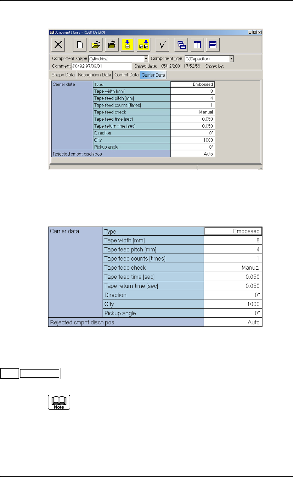
(A03_01) Carrier Data (Tape)
(1) Type
Select one of the following options as a type of a component carrier.
Paper Embossed Adhesive Vibratory Stick Tray
No types other than the above are used in TIM-X series.
A03 Carrier Data (A03_01)
0206-003 2-28 Tg0502-PM-CL
Fig. B45 Edit Window (Example) for Cylindrical Component
Fig. B46 Edit Window (Example) for Cylindrical Components
Embossed
Type
Fig. B47
(2) Tape Width [mm]
Select one of the following options as a tape width.
8 12 16 24 32 44 56 72
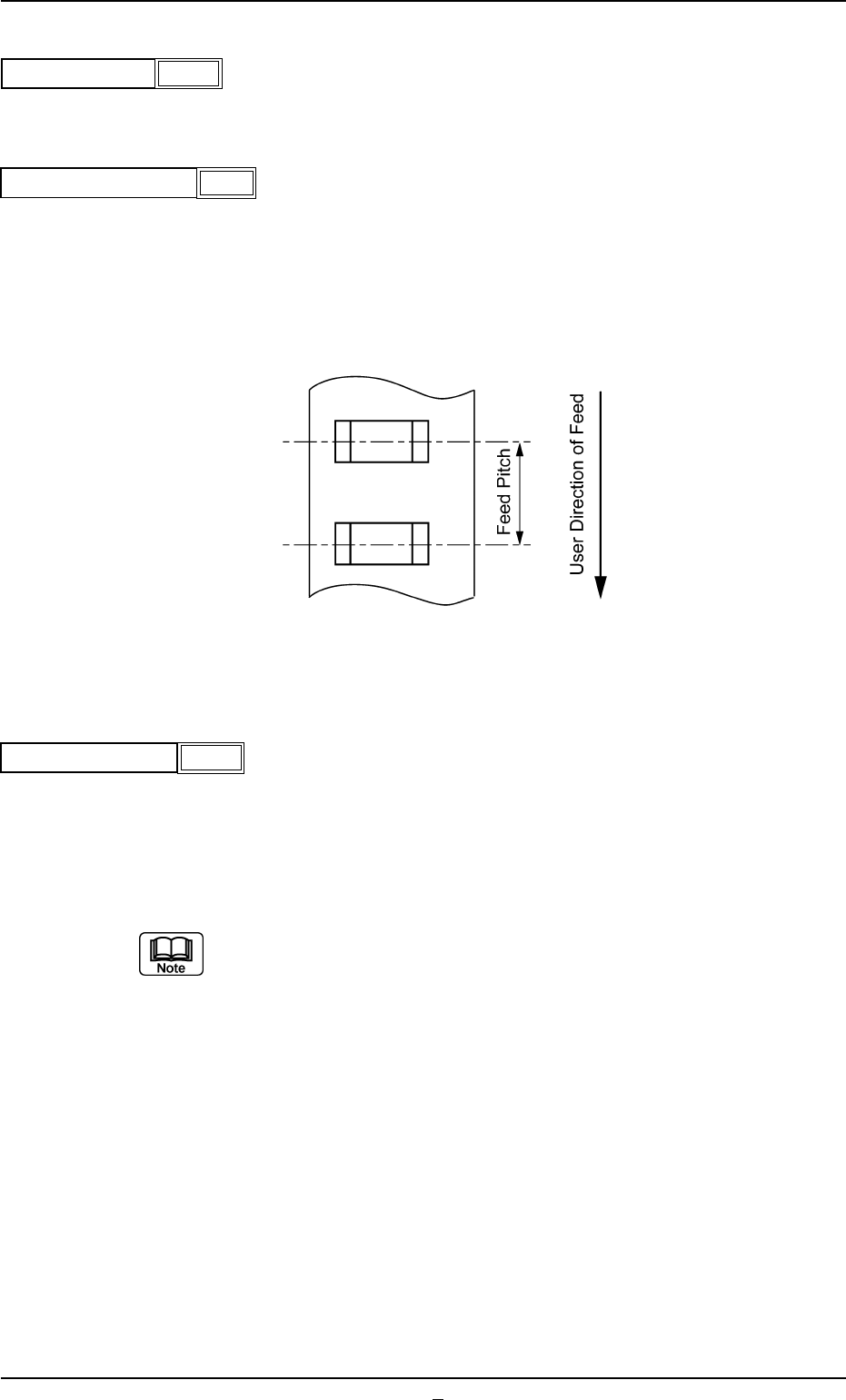
(3) Tape Feed Pitch [mm]
Select one of the following options as a tape feed pitch (a distance
between components).
Unit: mm
Data Input Range: 0 to 99
(4) Tape Feed Counts [times]
Set the number of tape feeding operations of the tape feeder.
Unit: times
Data Input Range: 1 to 9
(a) In the case of a tape feed pitch of 24 mm or more, and if two or more
feeding operations are required, set the number of operations for the
feeder.
(b) In general, for a feeder with a tape feed pitch of 2 to 20 mm, the
number of feeding operations is set to "1" (one).
A03 Carrier Data (A03_01)
0206-003 2-29 Tg0502-PM-CL
Fig. B50
4
Fig. B49
Tape feed pitch [mm]
8
Tape width [mm]
Fig. B48
Fig. B51
Tape feed Counts
1