OM-1076-001.pdf - 第58页
(4) Rejected Cmpnt Disch Pos Select one of the following options to designate the position from which the component must be discharged when a component cannot be placed due to a component recognition error . Auto, Recycl…
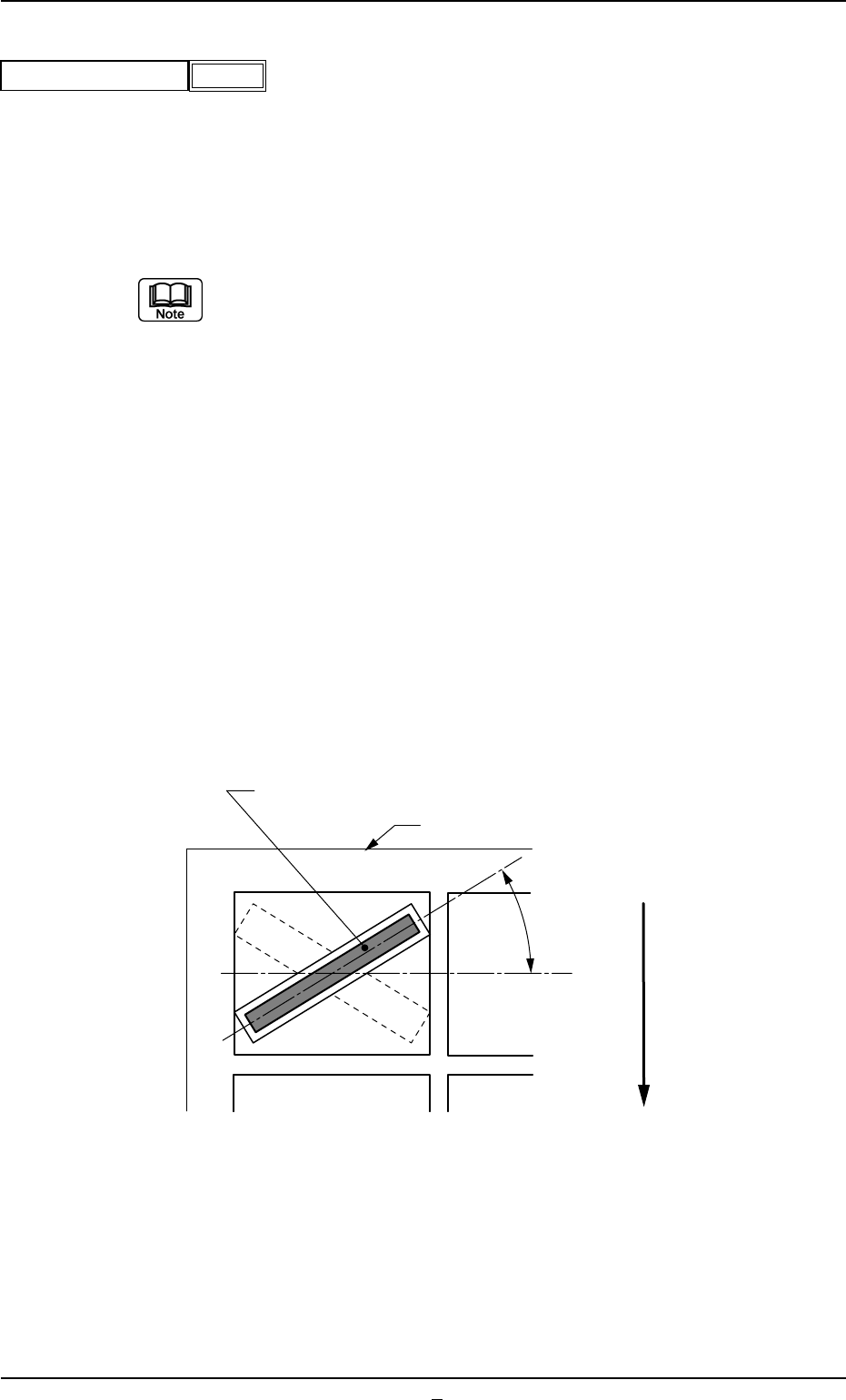
(3) Pickup Angle
Set the Angle at which the nozzle should be rotated before a compo-
nent is pickup.
Unit: ° (degree)
Data Input Range: -359° to +359°
(a) Use it for the components (connectors) placed diagonally because of
the restriction due to tray size . (Usually, set to +0*).
(b) When a value other than "0" (zero) is set in the data box, the dimen-
sions as component shape data (X, Y,..) are determined according to
the component posture (packaged posture) for component recogni-
tion.
(c) Set a value with "+" sign to implement the pick-up operation with a
nozzle pre-rotated counterclockwise.
(d) The nozzle is pre-rotated to the angle entered in this box and picks
up a component. When the component recognition is performed, the
nozzle is rotated back to "0" (zero) degree. The component posture
(the orientation of the component positioned by the nozzle rotated
back to "0" (zero) degree) must be set as a placement angle (pack-
age posture) in the pattern program.
Example: Shown below is a component (a connector) packaged on the
skew.
A03 Carrier Data (A03_03)
0206-003 2-34 Tg0502-PM-CL
-359
Pickup Angle
Fig.B71
Fig. B72
Component (Connector)
Tray
Pickup Angle
User Direction of feed
Top View of Component
(4) Rejected Cmpnt Disch Pos
Select one of the following options to designate the position from which
the component must be discharged when a component cannot be
placed due to a component recognition error.
Auto, Recycle Conveyor, Reject Box (Large)
In normal cases, select "Auto".
Select "Recycle Conveyor" only when the machine is equipped with the
recycle conveyor (option).
A03 Carrier Data (A03_03)
0206-002 2-34-1 Tg0502-PM-CL
Auto
Rejected cmpnt disch pos
Fig.B73
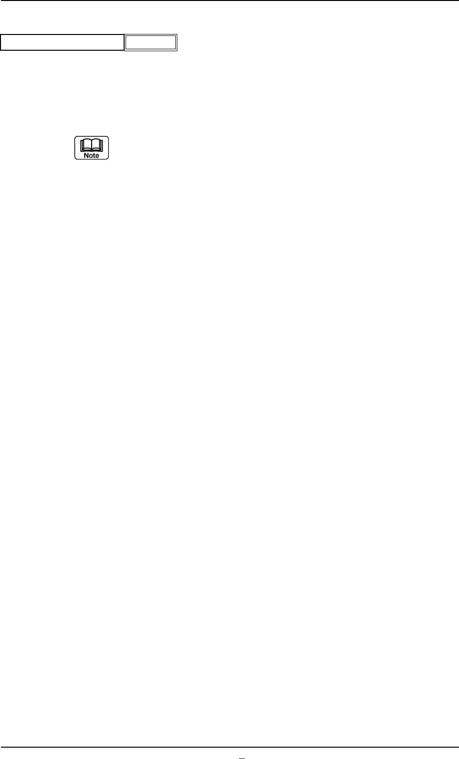
(5) Matrix Counts X, Y
Set the numbers of columns (X) and rows (Y) of the matrix in the data
box.
Data Input Range: 0 to 99
Components are picked up in the order of the matrix elements "(1, 1),
(1, 2), (1, 3),.. (2, 1), (2, 2),..", and so on.
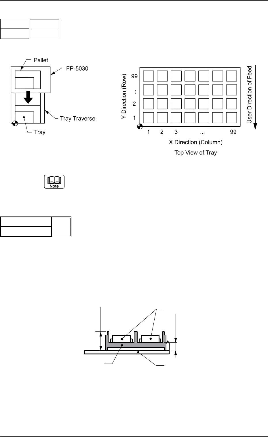
(6) Height H [mm], h [mm]
H : Set the distance (height) between the lower surface of the tray
and the upper surface of the tray in the data box.
h : Set the distance (height) between the lower surface of the tray
and the bottom of the cell (the cell in which a component is stored)
in the data box.
Unit: mm
Data Input Range: 0.01 to 99.99
A03 Carrier Data (A03_03)
0206-003 2-35 Tg0502-PM-CL
Fig. B74-1
Fig.B74
1
1
Matrix X
Matrix Y
Component
Pallet
Height h
Height H
Tray
Side View
Fig. B74-3
Fig.B74-2
0.01
0.01
Height
Height
H [mm]
h [mm]