OM-1076-001.pdf - 第63页
(1) X [mm] and Y [mm] Set Dimensions X and Y of the molded section. Unit: mm Leadless Components T op View of Component Data Input Range: X: 0.01 to 150.00 Y : 0.01 to 150.00 Leaded Components T op View of Component Data…
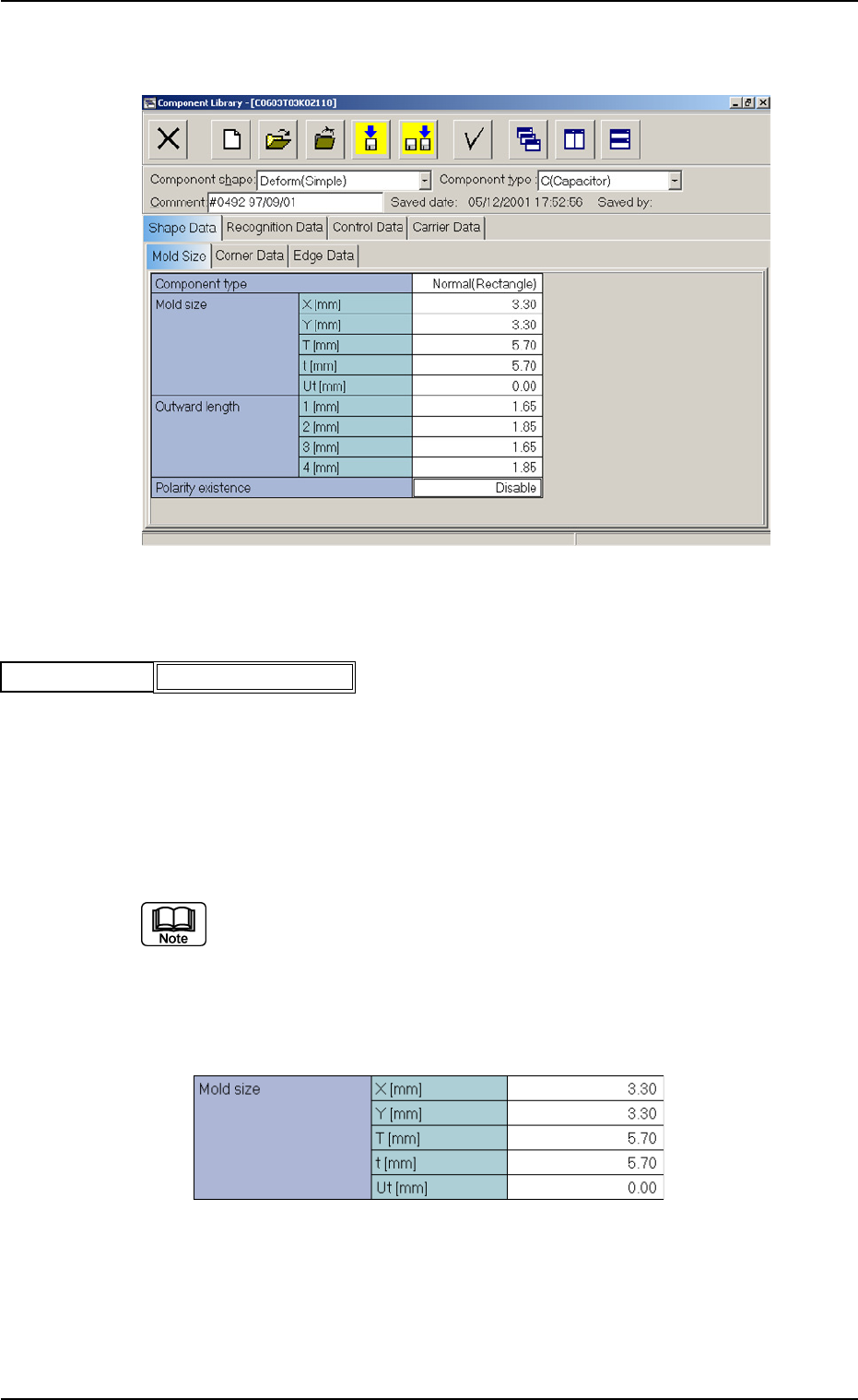
B01 Shape Data
(B01_01) Component Type
Select "Normal (Rectangle)" or "Round" as a component type.
Round : Select this when the component is completely round with-
out any polarity (directivity).
Example: Dielectric Element, etc.
Normal (Rectangle):
Select this for a component other than a round one.
In normal cases, select "Normal (Rectangle)".
Applicable Components: Deform (Simple)
(B01_02) Mold Size
B01 Shape Data (B01_01), (B01_02)
Fig. B76
Normal (Rectangle)
Component type
0111-002 2-38 Tg0502-PM-CL
Fig. B75 Edit Window (Example) for Deform (Simple) Components
Fig. B77 Edit Window (Example) for Cylindrical Components
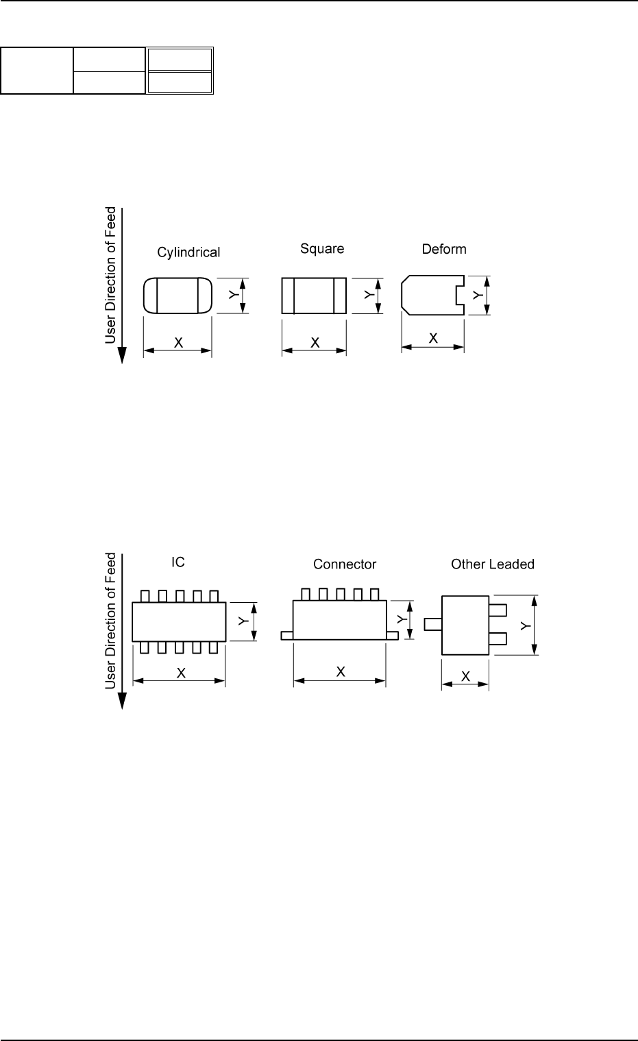
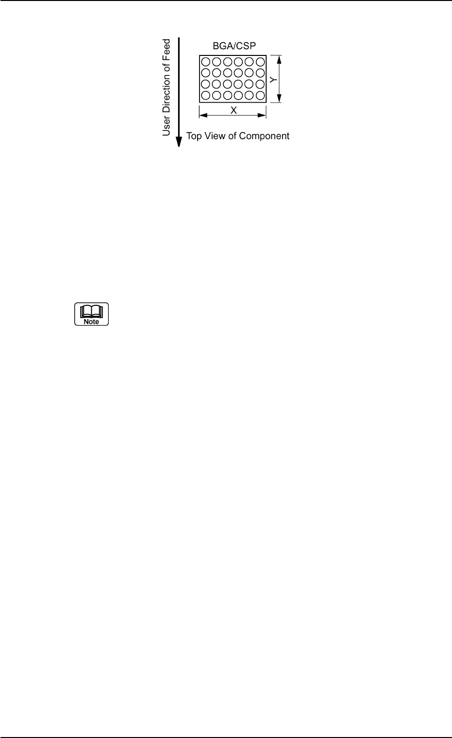
(1) X [mm] and Y [mm]
Set Dimensions X and Y of the molded section.
Unit: mm
Leadless Components
Top View of Component
Data Input Range:
X: 0.01 to 150.00
Y: 0.01 to 150.00
Leaded Components
Top View of Component
Data Input Range:
X: 0.01 to 150.00
Y: 0.01 to 150.00
B01 Shape Data (B01_02)
0206-002 2-39 Tg0502-PM-CL
Fig. B78
X [mm]
Y [mm]
3.30
3.30
Mold size
Fig. B79
Fig. B80
B01 Shape Data (B01_02)
0107-001 2-40 Tg0502-PM-CL
Data Input Range:
X: 0.01 to 150.00
Y: 0.01 to 150.00
Applicable Components : Cylindrical, Square, Deform (Simple), IC
(Simple), Connector (Simple), Other
Leaded (Simple), and BGA/CSP
Set a parameter in the "Y" text box only when "Normal (Rectangle)" is
selected in the "Cmpnt Type" text box for deform (simple) components.
Set a parameter only in the "X (diameter)" text box when "Round" is se-
lected in the "Component Type" text box.
Area Array
Fig. B81