OM-1076-001.pdf - 第68页
(B01_03) Outward Length 1 [mm], 2 [mm], 3 [mm], 4 [mm] Set the dimensions between the center of the mold and the outmost edges. The mark indicates the center of the mold. T op View of Component Unit: mm Data Input Range …
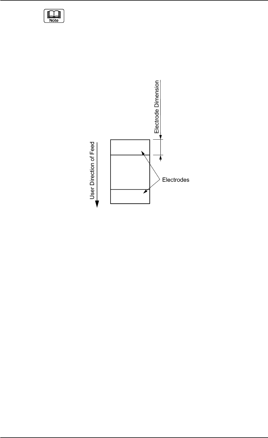
(a) Both right and left electrodes are identical in size.
(b) When the whole image of the component is reflected brightly, then
set this data to "0".
(c) When the electrodes are located in the user direction of component
feed as shown in the figure below, create each data as component
library data assuming that the electrodes are located as shown in the
figure above and set "90°" in the "Direction of the label "Carrier Data".
B01 Shape Data (B01_02)
0206-002 2-43 Tg0502-PM-CL
Fig. B88
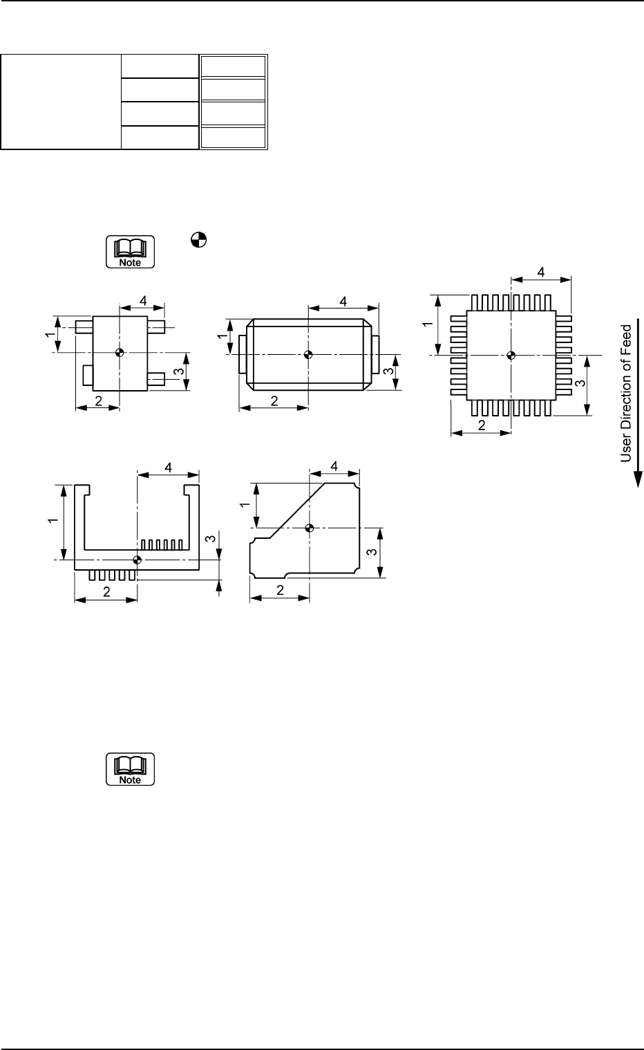
(B01_03) Outward Length 1 [mm], 2 [mm], 3 [mm], 4 [mm]
Set the dimensions between the center of the mold and the outmost
edges.
The
mark indicates the center of the mold.
Top View of Component
Unit: mm
Data Input Range: 0.01 to 150.00
(a) As for "Connector (Complex)" and "Other Leaded (Complex)", "Out-
ward Length 1, 2, 3, 4" and "Gp Ctr Pos (Latl Dir) n" & "Gp Prior Pos
(Long Dir) n" in "Lead Data" must be set based on the same refer-
ence position.
(b) As for the deform (complex) components, the reference position to
set parameters for "Outward Length" must be the same as the refer-
ence position to set parameter "St Coord X and Y" in "Linear Edge
Data".
Applicable Components : Deform (Simple), Deform (Complex), IC
(Simple), IC (Complex), Connector (Simple),
Connector (Complex), Other Leaded
(Simple), and Other Leaded (Complex)
B01 Shape Data (B01_03)
0107-001 2-44 Tg0502-PM-CL
Outward length
1.65
1.85
1.65
1.85
Fig. B89
1 [mm]
2 [mm]
3 [mm]
4 [mm]
Fig. B90
(B01_04) Polarity Existence
Set "Enable" or "Disable" to determine whether or not the component
has a polarity (direction).
This data is used for optimization of the pattern program.
Applicable Components:
Applicable for all subjected components
This data is used for optimization of pattern program.
Refer to the instruction manual "Optimization Software" for details.
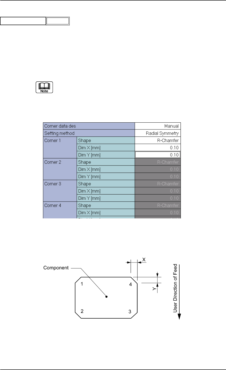
(B01_05) Corner Data
Set the shape of component corners and dimensions X and Y.
Top View of Component
B01 Shape Data (B01_04), (B01_05)
Fig. B91
Polarity existence Enable
0111-002 2-45 Tg0502-PM-CL
Fig. B92 Edit Window (Example) for Cylindrical Components
Fig. B93