OM-1076-001.pdf - 第74页
(1) Shape Select the following parameters (edge shapes at each detectable po- sition). T able B13 Straight Convexoconcave No Detection Select this when the component mold has slanted edges (not straight) and the edge det…
(B01_06) Edge Data
Set edge shapes at each detectable position in the "Shape", "Detec-
tion Posn X", and "Detection Posn Y" for Edges "1", "2", "3", and "4".
Be sure to select two or more edges and set parameters for them as
edge data.
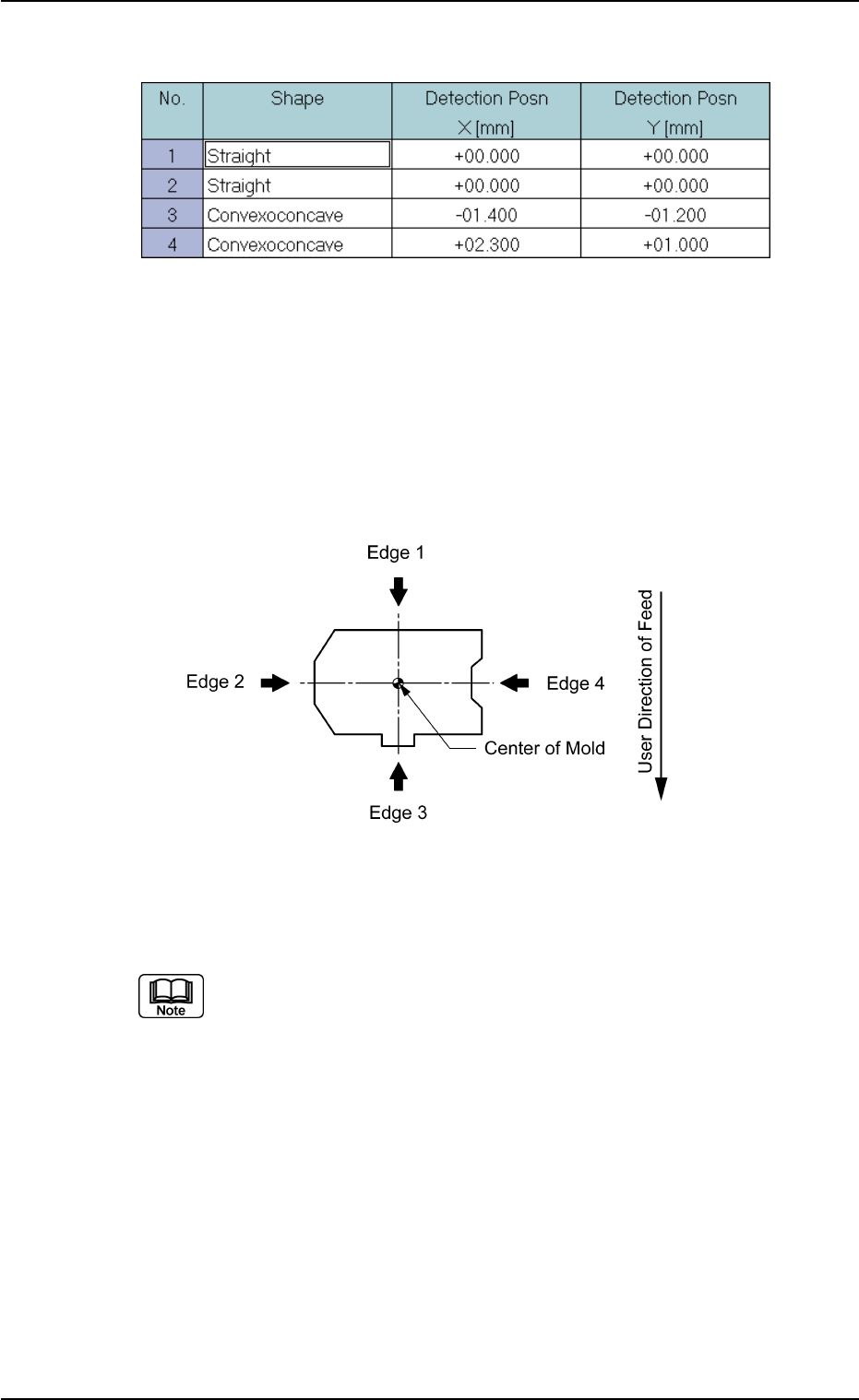
• Edges 1, 2, 3, and 4
The following shows the positional relation of a component based
on the packaged posture.
Top View of Component
Applicable Components: Deform (Simple)
Set parameters only when "Normal (Rectangle)" is selected in the "Cmpnt
Type" text box.
B01 Shape Data (B01_06)
0107-001 2-49 Tg0502-PM-CL
Fig. B101 Edit Window (Example) for Deform (Simple) Components
Fig. B102
(1) Shape
Select the following parameters (edge shapes at each detectable po-
sition).
Table B13
Straight
Convexoconcave
No Detection Select this when the component mold has
slanted edges (not straight) and the edge
detection positions described in "(2) Detec-
tion Posn X and Y" cannot be specified. In
this case, the component center is calcu-
lated based on the result of the opposite
edge detection and according to the com-
ponent size.
Components without any straight edge cannot be recognized by the edge
detection function.
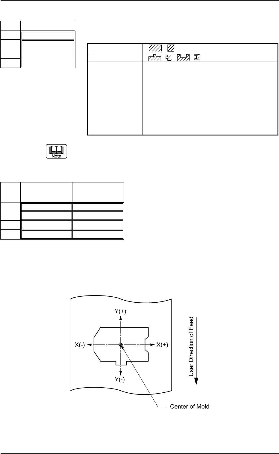
(2) Detection Posn X [mm] and Y [mm]
Set edge detectable positions X and Y originating from the center of
the mold.
When the center of the mold is assumed as an origin, the sign "+" or "-
" must be affixed to the coordinates of the edge detectable position as
shown below.
Top View
B01 Shape Data (B01_06)
0107-001 2-50 Tg0502-PM-CL
Fig. B103
Shape
Straight
Straight
Convexoconcave
Convexoconcave
No.
1
2
3
4
Fig. B104
Detection Posn
X [mm]
+00.000
+00.000
-01.400
+02.300
Detection Posn
Y [mm]
+00.000
+00.000
-01.200
+01.000
No.
1
2
3
4
Fig. B105
(a) Set parameters only when "Convexoconcave" is selected in the
"Shape" text box.
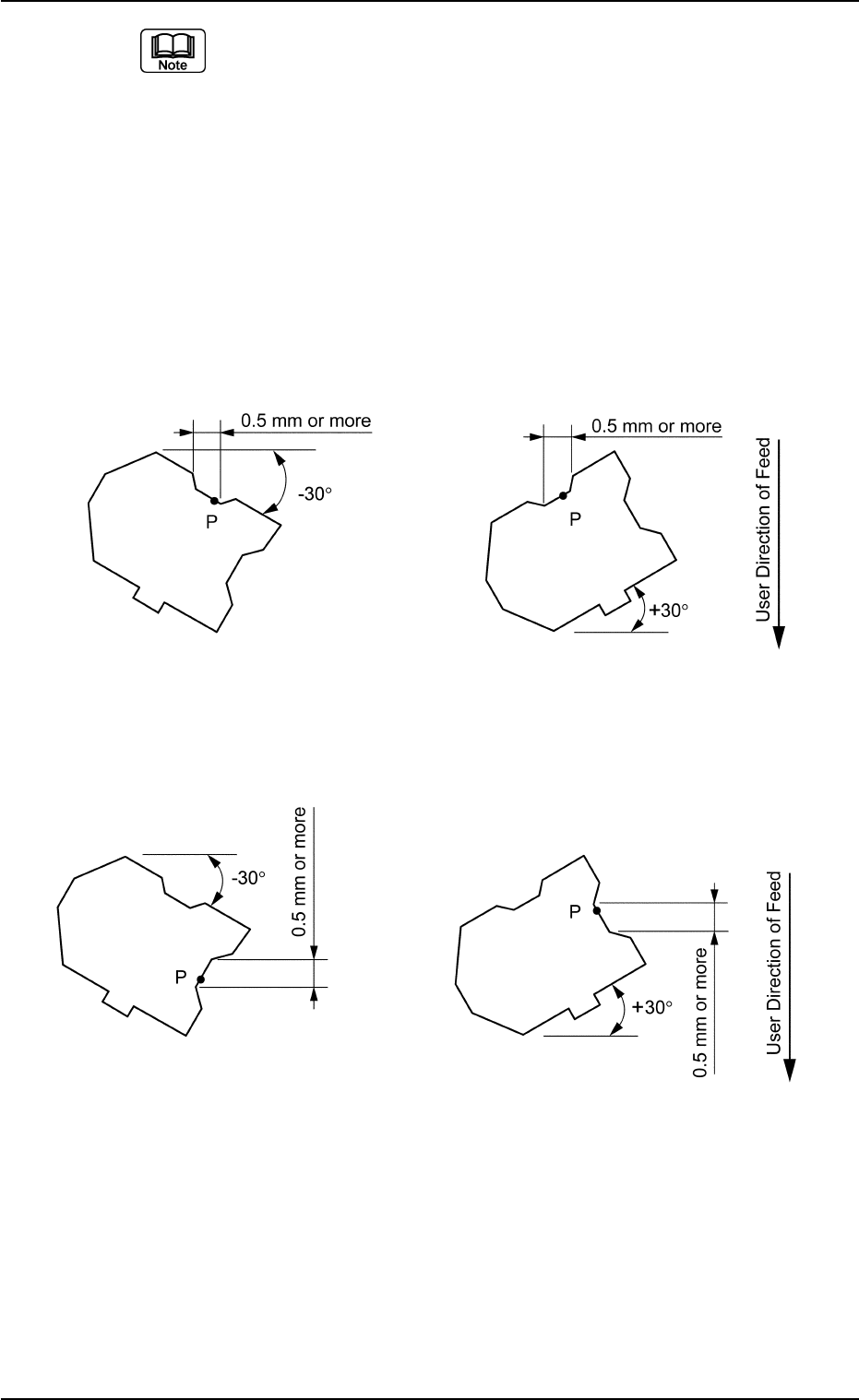
(b) Detectable Point P is the point that meets the following two require-
ments.
It is recommended that Detectable Point P should be located as close
to a corner as possible.
• Point P must be on a straight line parallel to the detection edge and
the length of the line must be 0.5 mm or more.
• If there is a projection nearby, a space of at least 0.5 mm must be
assured in the X or Y element when the component is tilted ±30°
(approx.) as in the figures below.
Case: X Element
Top View of Component
Fig. B106
Case: Y Element
Top View of Component
Unit: mm
Data Input Range
X: −99.999 to +99.999
Y: −99.999 to +99.999
Applicable Components: Deform (Simple)
0206-002 2-51
Tg0502-PM-CL
B01 Shape Data (B01_06)
Fig. B107