OM-1076-001.pdf - 第79页
B01 Shape Data (B01_07) 0107-001 2-55 Tg0502-PM-CL (e ) It is recommended that the parameters related to linear edges be defined counterclockwise for easier management, starting with "Edge 1". Example: As for t…
B01 Shape Data (B01_07)
0107-001 2-54 Tg0502-PM-CL
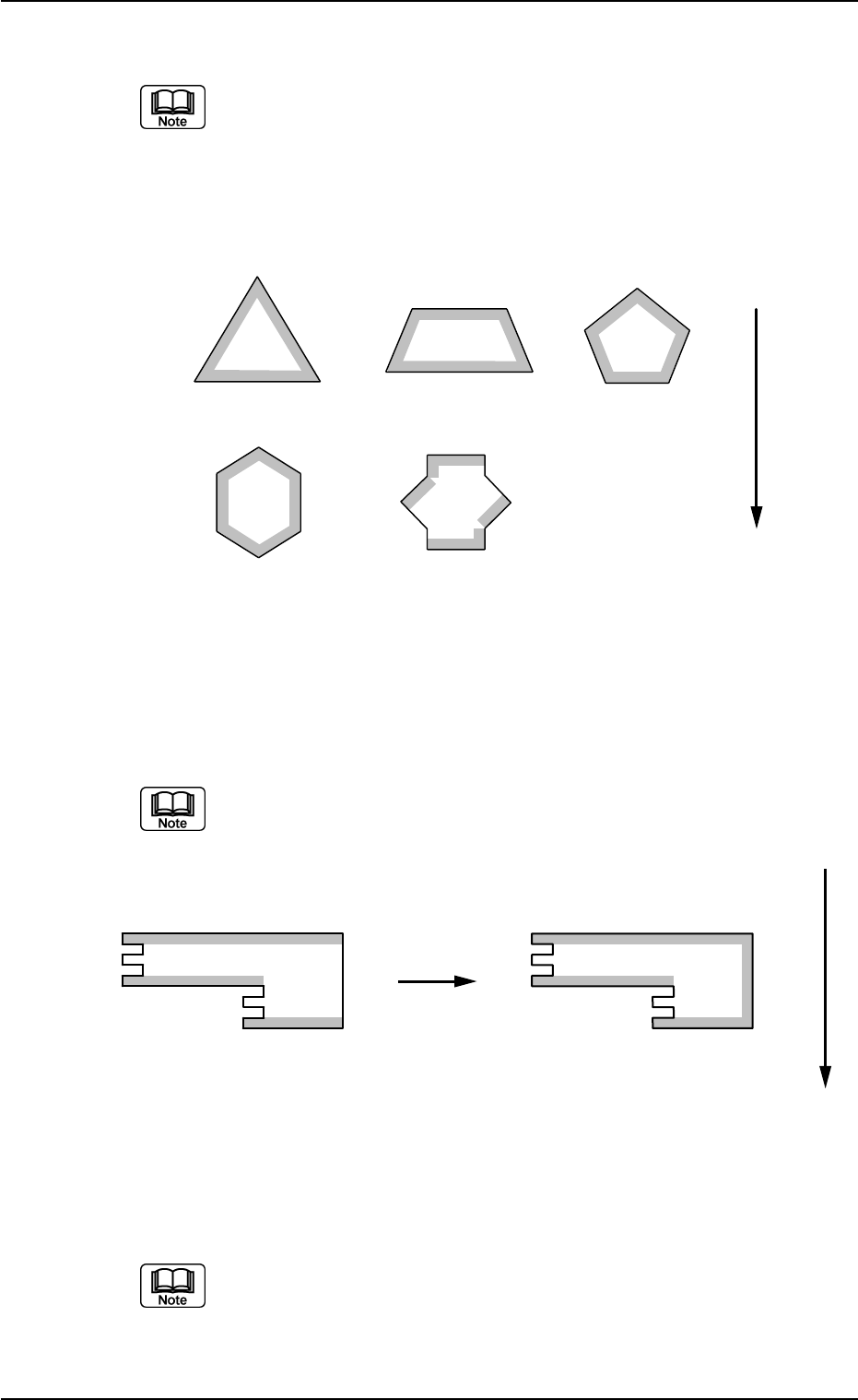
(b) Up to 6 linear edges (3 to 6) must be specified.
(a) The more edges are defined, the higher accuracy can be expected.
However, longer processing time will be required in proportion to the
specified number of edges.
(b) The figures show the linear edge Nos.
Example:
1
2
3
1
2
3
4
1
2
3
4
5
1
2
5
4
6
1
2
3
4
5
6
3
Top View of Component
User Direction of Feed
(c) Select linear edges which have interior angles close to 90°, each
formed by a side and the extension of an adjacent side.
At least one edge must be shifted from the other one by 45 to 135° or 225
to 315°
1
2
3
1
2
3
4
Top View of Component
OKNG
User Direction of Feed
(d) Select linear edges which are 2.0 mm or more in length.
An edge must be perfectly straight without any irregularity.
Fig. B110
Fig. B111
B01 Shape Data (B01_07)
0107-001 2-55 Tg0502-PM-CL
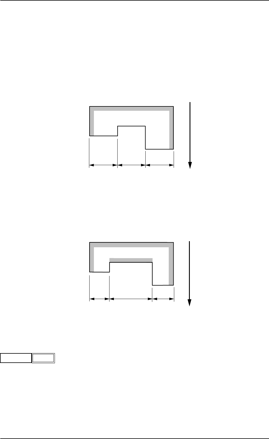
(e) It is recommended that the parameters related to linear edges be
defined counterclockwise for easier management, starting with "Edge
1".
Example: As for the component shown below, the shadowed edges must
be selected.
Select "1", "2", or "3" (indicated in the figure below) as the last
remaining edge.
Any one of "1", "2", and "3" can be selected, causing no hin-
drance to the recognition.
2
3
1
a
a
a
Top View of Component
User Direction of Feed
However, when "1", "2", and "3" have different dimensions in length,
the selection of the longest linear edge will improve the accuracy of
the recognition.
(b<c)
2
3
1
b
c
b
Top View of Component
User Direction of Feed
(1) # of Edges
Set the number of linear edges.
Data Input Range: 3 to 6
# of Edges
Fig. B114
3
Fig. B112
Fig. B113
B01 Shape Data (B01_07)
0206-002 2-56 Tg0502-PM-CL
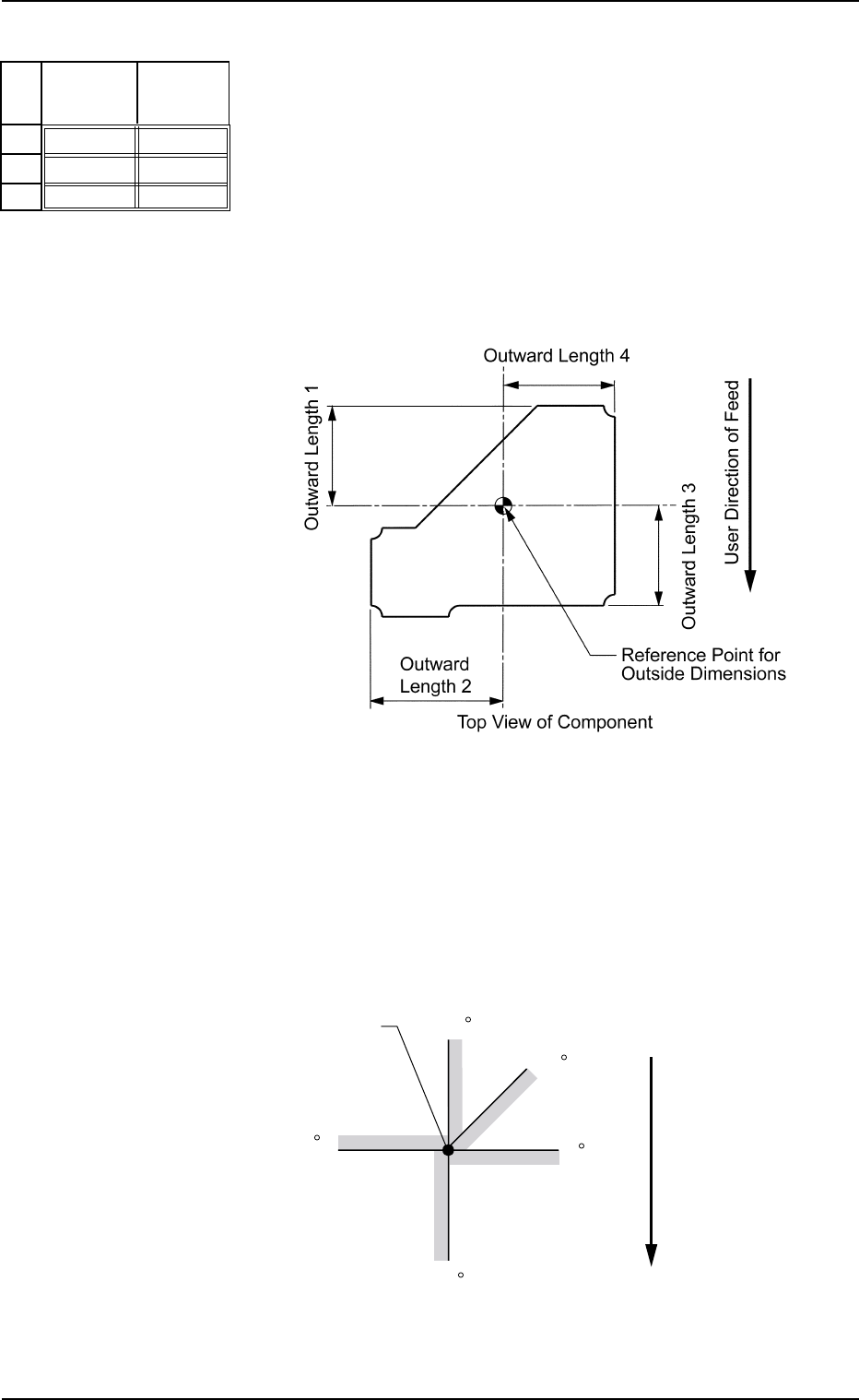
(2) Stg Coord X [mm], Y [mm]
Set the start position (coordinates X and Y) of the selected linear edge
in each data box.
Enter the distance from the reference position determined by the pa-
rameters in the "1", "2", "3", and "4" data boxes of the label "Outward
Length" (described in "Outward Length 1, 2, 3, 4").
Unit: mm
Data Input Range:
Xn: −99.999 to +99.999
Yn: −99.999 to +99.999
Fig.B115
Stg Coord
Y [mm]
+00.000
+00.000
+00.000
Stg Coord
X [mm]
+00.000
+00.000
+00.000
No
1
2
3
• Definition of Start Position (Coordinates X and Y)
The start position (coordinates X and Y) is determined according to
the selection of the lighting system ("Back Ltg" or "Front Ltg"), and
the brightness at both sides of set edges.
See the figure below for your reference and determine the start po-
sition (coordinates X and Y).
Straight Lines: Linear Edges
Fig. B116
Fig. B117
90
45
0
180
270
Start Position
Top View
User Direction of Feed